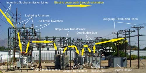
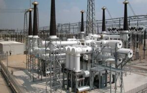
An electrical substation is an integral part of a generation, transmission and distribution system. A substation can interrupt or establish electrical circuit, change the voltage, frequency or other characteristics of electrical energy flowing in the circuit.
In this article you will learn different types of substations, their functions and different equipment used used in them.
What is Substation?
A substation is an installation that interconnects elements of an electric utility’s system. These elements can include generators, transmission lines, distribution lines, and even neighboring utility systems.
It is common to refer to the transmission and distribution elements as networks or again, as systems.
Depending on the size and complexity of a particular utility system, the transmission and/or distribution networks may include more than one voltage level.
For instance, a utility’s transmission network may include 115 kV and 230 kV transmission lines, while another utility’s distribution network may include both 13.8 kV and 34.5 kV distribution lines.
The substation provides the interconnection of transmission circuits and the transformation between the network of different voltages.
The substation is connected to the network through overhead lines. In some cases, it may not be possible to make a connection to the substation directly by the overhead line and underground cable entry must be considered.
Electrical Substations have the following mission to accomplish:
- Step-up and step-down voltage transformation
- Connection of separate transmission and distribution lines into a system to increase efficiency and reliability of power supply.
- Sectionalizing of the power system to increase its reliability and operational flexibility – substation called “switching substation”
The different substation configurations are characterized by their busbar arrangements and generally, any number of circuits may be provided by repeating the pattern.
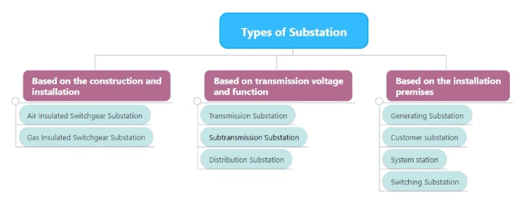
Types of Substation
There are many kinds of ac substations. They are classified into different types based on various criteria. Some of them are discussed below.
Based on the construction and installation of switchgear, electric substations are of two types.
- Air Insulated Switchgear Substation (Open Terminal Substation)
- Gas Insulated Switchgear Substation (Metal Clad Substation)
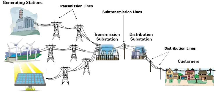
Based on transmission voltage and function, the electric substation is classified into three types.
- Transmission Substation
- Subtransmission Substation
- Distribution Substation
Based on the installation premises there are four major types of substations.
- Generating Substation
- Customer Substation
- System Station
- Distribution Station
- Switching Substation
- Generating station substations transform generation voltage (usually 15 kV through 23 kV) up to transmission network voltage (usually 69 kV through 500 kV).
- Transmission switching substations interconnect portions of the utility system transmission network but do not include transformation between voltage levels.
- Transmission step-down (or step-up, depending on your point of view) substations interconnect portions of the utility system transmission network and include transformation between transmission network voltage levels.
- Distribution step-down substations may or may not interconnect portions of the utility system transmission network, include transformation between transmission network and distribution network voltage levels, and interconnect portions of the utility system distribution network.
- Distribution substations interconnect portions of the utility system distribution network and may include transformation between distribution voltage levels.
DC interconnections are made with one of two specialized types of substations. These dc interconnections are not common and are much higher in capital cost than comparable ac interconnections.
- The first type, ac/dc or dc/ac conversion stations, interconnects the ac transmission network of one utility system with a dc transmission line or network. The dc line or network connects with one (or more) other conversion stations.
- The second type, ac/dc/ac (back-to-back) conversion stations, interconnect the ac transmission network of one utility system with the ac transmission network of another utility system. In effect, this is two conversion stations on the same site with the dc transmission line inside the converter building.
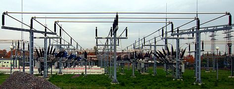
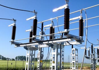
1. Air Insulated Substation
Air Insulated Switchgear Substation, as the name suggests, utilizes primary substation equipment whose terminals are in the air.
Consequently, large clearances are required between these terminals and earth and between terminals of different phases. As a result, the ‘air-insulated / open terminal’ substations occupy relatively large areas of land.
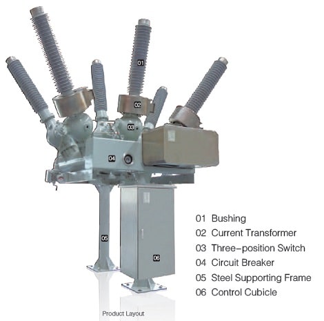
2. Gas Insulated Substation
Gas Insulated Substation or metal-clad equipment utilizes either solid or gaseous (SF6) insulation to allow the phase to earth and phase to phase clearance to be drastically reduced.
The space-saving advantages of gas-insulated/metal-clad equipment can be significant particularly for high voltage substations in large cities where space is difficult to obtain and the land is very expensive.
Metalclad equipment may also be attractive for other reasons, notably visual impact in environmentally sensitive areas and operation in heavily polluted environments.
Air-insulated substations generally cost less than an equivalent gas insulated substation.
Almost all Gas Insulated Switchgear substations are built indoor. GIS can be easily built underground to avoid any environmental concern. The internal GIS insulation is independent of atmospheric pressure.
3. Transmission Substation
The transmission substation transformers support the transmission system and the smaller sub-transmission and distribution substation transformers.
The transmission substation contains equipment used to sectionalize the electric transmission system when a fault or short circuit develops on one of the circuits.
Circuit breakers in the transmission substation are used to switch generating and transmission circuits in and out of service. The faulted circuit is switched out of service automatically and de-energized, protecting the remaining portion of the transmission network from trouble.
4. Sub transmission Substation
Electric substations with equipment used to convert high-voltage, extra-high-voltage (EHV), or ultra-high-voltage (UHV) transmission lines to the intermediate voltage sub-transmission lines or to switch sub-transmission circuits operating at voltages in the range of 34.5 kV to 161 kV are referred to as sub-transmission substations.
Sub transmission circuits and substations are located near to high-load concentrations, usually in urban areas. Sub transmission circuits supply distribution substations.
5. Distribution Substation
Substations located in the middle of a load area are called distribution substations. These substations may be as close together as 2 miles in densely populated areas.
The substations contain power transformers that reduce the voltage from sub-transmission levels to distribution levels, usually in the range of 4.16Y/2.4 kV to 34.5Y/19.92 kV.
The transformers are normally equipped to regulate the substation bus voltage. Circuit breakers or circuit reclosers in the distribution substations are installed between the low-voltage bus and the distribution circuits.
The distribution circuits vary in capacity from approximately 5 MVA to 20 MVA (1 MVA = 1000 kVA).
Large distribution substations have power transformers with a capacity as large as 100 MVA and serve as a source to as many as 10 distribution circuits. Read the difference between power transformers and distribution transformers.
If the power transformers do not have automatic tap-changing underload equipment, it is usually necessary to install voltage regulators.
These above-mentioned substations are explained in major types of substations.
| Substation Type | Description |
|---|---|
| Air Insulated Switchgear Substation | Utilizes primary substation equipment with terminals in the air. Requires large clearances and occupies significant land area. |
| Gas Insulated Switchgear Substation | Uses solid or gaseous (SF6) insulation, reducing clearances and saving space, suitable for high voltage substations in urban areas. |
| Transmission Substation | Supports the transmission system and sectionalizes circuits during faults. Contains circuit breakers for switching circuits. |
| Subtransmission Substation | Converts high-voltage transmission lines to intermediate voltage sub-transmission lines or switches sub-transmission circuits. |
| Distribution Substation | Located in load areas, reduces voltage to distribution levels. Contains power transformers, circuit breakers, and voltage regulation. |
Functions of a Substation
A substation performs a major role in our power system. The functions of a substation may include one or more of the following:
- To isolate a faulted element from the rest of the utility system.
- To allow an element to be disconnected from the rest of the utility system for maintenance or repair.
- To change or transform voltage levels from one part of the utility system to another.
- To control power flow in the utility system by switching elements into or out of the utility system.
- To provide sources of reactive power for power factor correction or voltage control.
- To provide data concerning system parameters (voltage, current flow, power flow) for use in operating the utility system.
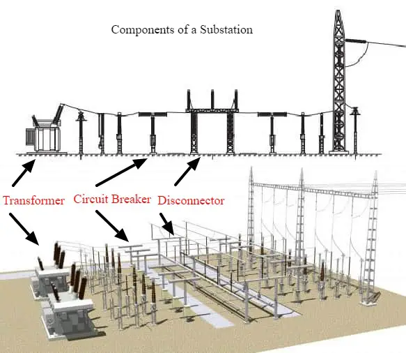
Substation Equipment / Components
An electrical substation contains many types of equipment. Substation generally comprises the following equipment:
- Power Transformers
- Tap Changing Equipment
- Circuit Breakers
- BusBar, Bays and Steel Structures
- Lightning Arrester
- Circuit Switchers
- Disconnect Switch / Isolator
- Earth Switches
- Current Transformer
- Potential Transformer
- Neutral Grounding Resistor
- High Voltage Fuses
- Metal-Clad Switchgear
- Shunt Reactors
- Current-Limiting Reactor or Series Reactor
- Line Trap
- Coupling Capacitor Voltage Transformer
- Control House
- Control Panel
- Substation Protective Relays
- Supervisory Control
- Remote Terminal Unit
- Digital Fault Recorder
- Capacitor Bank
- Voltage Regulator
- Power-Line Carrier Equipment
- Microwave Equipment
- Batteries
To fulfill the function of a substation, they include a wide variety of equipment. Each of them will be explained in the next subsections.
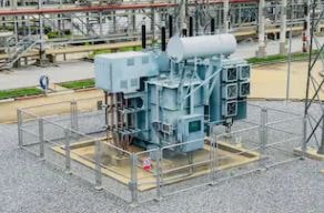
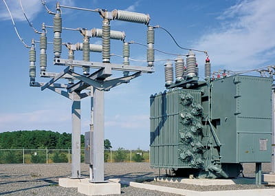
Power Transformers
Power transformers are the most important equipment in an electrical substation. They are different from distribution transformers.
They perform different functions. They are used to
- change the voltage from one level to another,
- to regulate the voltage level,
- and to control the flow of reactive kilovolt-amperes in the power system.
Power transformers installed in transmission substations will normally be constructed for and operate at voltages in the range of 138,000 volts to 765,000 volts or higher.
Most substations will have three-phase transformers. Some substations will have three single-phase transformers in parallel installed in a bank.
Often, a fourth single-phase transformer will be located at the substation to serve as a spare. If one of the transformers connected in the bank fails, the spare is energized to expedite the restoration of electric service.
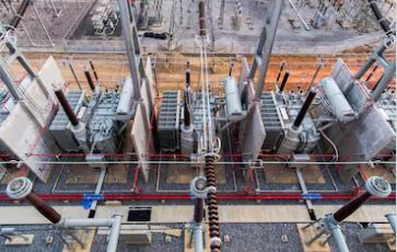
The capacity of the transmission substation transformers will normally be in the range of 1,000 MVA to 50 MVA.
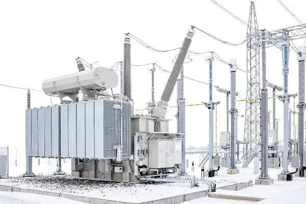
Power transformers installed in distribution substations will normally be constructed for and operate at the lower voltages and smaller capacities. The voltages will generally be in the range of 161,000 volts to 4,160 volts and the capacities in the range of 50 MVA to 5 MVA.
The figure given is a picture of a power transformer that is part of a distribution substation.
Tap Changing Equipment
Optional equipment that may be added to the substation transformer is tap changing equipment.
There are two types of tap changers.
- On load tap changer
- Off load tap changer
The tap changer feature allows the voltage to be adjusted in increments as system-loading conditions require.
The controls of the tap changing equipment are installed in a panel mounted on the side of the power transformer. Remote control of the tap changing equipment is usually installed as well.
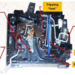
Circuit Breakers
High Voltage and Medium-voltage switchgear such as oil circuit breaker, SF6 circuit breaker, air circuit breaker, gas circuit breaker, and vacuum circuit breakers are used to switch electric circuits and substation equipment in and out of the system.
A circuit breaker is a mechanical switching device, capable of making, carrying and breaking currents under normal circuit conditions and also making, carrying for a specified time and breaking currents under specified abnormal circuit conditions such as those of short circuit.
The contacts of the circuit breakers are opened and closed by mechanical linkages manufactured from insulating materials and utilizing energy from compressed air, electric magnets, or charged springs.
Some of the high-voltage circuit breakers utilize compressed air to operate the contacts and interrupt the current flow when the contacts are open.
Operation of the circuit breakers is initiated, utilizing dc circuits, by manually operating a switch, by remote operation of supervisory control equipment, or by relays that automatically recognize predetermined abnormal conditions or electrical failures in the system.
Various types of circuit breakers used in high voltage substations are.
There are low voltage circuit breakers like MCB and GFCI that are not normally used in high voltage substations. MCBs are used inside the control panels.
BusBar, Bays and Steel Structures
The substation buses are current-carrying devices that interconnect the individual pieces of substation equipment.
The substation bus tubing (or bus bar) is aluminum or copper. Steel structures provide support for insulators, which are used to terminate lines, and support buses.
Disconnect switches and other equipment are mounted on the steel structures.
Read more about busbar configuration in a substation.
Lightning Arrester
The lightning arresters are another important substation switchgear equipment that protects the electric system and the substation equipment from lightning strikes and switching surges.
The lightning arresters are installed in a substation near the termination of aerial circuits and close to the more valuable pieces of equipment, such as power transformers.
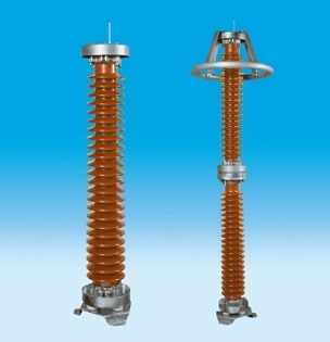
The power transformer has lightning arresters mounted on the radiators which are connected to both the 345 kV and 138 kV transformer bushings.
Lightning arresters contain semiconductor blocks, which limit the magnitude of high-surge voltages, permit the large-surge currents to pass harmlessly to the ground, and interrupt the power-follow current after the surge is eliminated.
Metal-oxide surge arresters function like a ceramic capacitor at normal line voltage, limiting the flow of current to ground.
When a high voltage begins to build up across the semiconductor blocks, they provide a low-impedance path to ground, which permits the surge current to flow to ground, limiting the voltage buildup and preventing the equipment from being damaged. The semiconductor blocks in the arresters are manufactured using zinc oxide material.
Circuit Switchers
According to IEEE, Circuit Switcher is a mechanical switching device with an integral interrupter, suitable for making, carrying, and interrupting currents under normal circuit conditions.
Circuit switchers are also known as load interrupter switch or line circuit breaker.
Circuit switcher is a device that combines a disconnect switch with an SF6 interrupter. This device has the ability to switch electrical loads (energized circuits) and limited fault current interrupting capability. In a single device, it offers isolation and limited fault interrupting capability.
If the voltage is less than 500 kV, circuit switchers usually have a common structure supporting three phases (AC). For voltages above 500 kV, a common structure is too wide, and each phase has its own structure. A control junction box and operating mechanism are supported by structure legs.
The circuit switcher imparts a dynamic load when it opens or closes, and the structure should be rigid enough to allow proper switching.
It is also suitable for interrupting specified short-circuit current that may be less than its close and latch, momentary, and short-time current ratings.
Circuit switchers employ SF6 puffer-type interrupters for switching and protection of transformers, lines, cables, and capacitor banks and have fault-interrupting ratings suitable for use in protecting medium- to large load transformers. Models are available with and without integral disconnect switches.
Circuit Switcher vs Circuit Breaker
Now you may be confused about the difference between Circuit Breaker and Circuit Swither. Circuit Switchers are different from the circuit breakers. Circuit switcher is an economic solution adopted for switching substation equipment (eg: transformer). They are cheaper and generally have a lower interruption rating compared to circuit breakers.
Circuit switchers are typically used on distribution transformer primaries where fuses were typically used in the past. The use of a circuit switcher in place of fuses is a major improvement in protection. For most of these applications, there is no way that the cost of a 115 kV or 230 kV circuit breaker could be justified.
The circuit switcher has the following benefits over circuit breaker: Compact, low cost, and some models include a visible break switch in their operation.
Drawbacks over a circuit breaker include low-speed reclosing, and not designed for high-operation environments.
The operation of circuit switchers is initiated by manually operating a switch, by remote supervisory control equipment, or by substation protective relays that automatically sense abnormal predetermined system or equipment conditions or electrical failures (faults).
Circuit switchers serve to provide reliable, economical switching and protection for transformers, single-shunt capacitor banks, line-connected, and testing connected shunt reactors, lines, and cables.
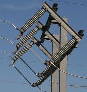
Disconnect Switch / Isolator
Disconnect switches (Isolators) are devices that are generally operated off-load to provide isolation of main plant items for maintenance, on to isolate faulted equipment from other live equipment.
Air Insulated or open terminal disconnectors are available in several forms for different applications.
At the lower voltages, single break types are usual with either ‘rocker’ type or single end rotating post types being predominant.
At higher voltages, rotating center post, double end rotating post, vertical break, and pantograph type disconnectors are more common. Air break switches are used in lower voltage to disconnect on load.
Disconnectors are usually interlocked with the associated circuit breaker to prevent any attempt being made to interrupt load current. Disconnectors are not designed to break fault current although some designs will make fault current.
Most disconnectors are available with either a manual drive mechanism or motor operated drive mechanism and the appropriate drive method must be selected for a particular disconnector in a particular substation.
For example, in a remotely controlled unmanned double busbar substation the busbar selector disconnectors would be motor operated to allow ‘on load’ busbar changes without a site visit being required.
Disconnector mechanisms incorporate a set of auxiliary switches for remote indication of disconnector position, electrical interlocking and current transformer switching for busbar protection.
Earth Switches
Earthing switches are usually associated and interlocked with disconnectors and mounted on the same base frame. They are driven by a separate, but similar, mechanism to that used for the disconnector.
This arrangement avoids the need for separate post insulators for the earth switch and often simplifies interlocking.
Normally earth switches are designed to be applied to dead and isolated circuits and do not have a fault making capability, however special designs are available with fault making capability if required.
One practical point worth noting is that line or cable circuit earth switches are normally interlocked with the local line disconnector, but reliance is placed on operating procedures to ensure that the circuit is isolated at the remote end before the earth is applied.
Current Transformer
A current transformer (CT) is a type of transformer that is used to measure AC. It produces an alternating current (AC) in its secondary which is proportional to the AC current in its primary.
The Current Transformer is one of the substation equipment used to convert the primary power signal to manageable values for metering systems, recording systems, protective relay systems, power generation, plant monitoring systems, SCADA and load control.
Current transformers are used extensively for measuring current and monitoring the operation of the power grid.
The primary winding of a current transformer is connected in series with the high-voltage conductor. The magnitude of amperes flowing in the high-voltage circuit is reduced proportionately by the ratio of the transformer windings.
The secondary winding of the current transformer is insulated from the high voltage to permit it to be connected to low-voltage metering circuits.
Current and potential transformers supply the intelligence for measuring power flows and the electrical inputs for the operation of protective relays associated with the transmission and distribution circuits or equipment such as power transformers.
Read more on Current Transformers.
Potential Transformer
High voltages in the substation are measured by reducing the voltage proportionately with equipment called a potential transformer.
Its high-voltage winding connected to the transmission or distribution circuit and its low-voltage winding connected to a meter or relay or both.
Potential transformers are required to provide accurate voltages for meters used for billing industrial customers or connecting utility companies. If single-phase transformers are used, three transformers are generally required to measure power on a three-phase circuit.
Neutral Grounding Resistor
The neutral grounding resistor provides resistance grounding of the neutral transformers to limit ground fault current to a value that does not damage generating, distribution, or other associated equipment in the power system, yet allows sufficient flow of fault current to operate protective relays to clear the fault.
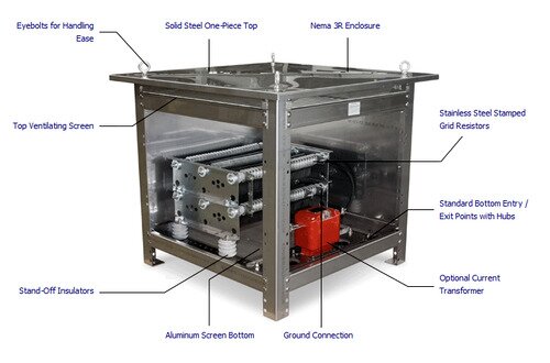
With solid grounding, the system is directly grounded, and the fault current is limited only by the soil resistance. Fault currents can be very high, causing damage to transformers, generators, motors, wiring, and other equipment. A Neutral Grounding Resistor is inserted between neutral and ground in order to increase the net resistance in the event of an earth fault, thus limiting the current.
Neutral Grounding Resistors are sometimes mounted on separate structures but are usually mounted on the transformer tank.
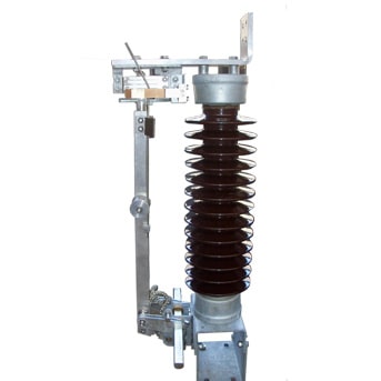
High-Voltage Fuses
High-voltage fuses are used in substations to protect the electrical system from faults in such equipment as potential transformers or power transformers.
A group operated high-voltage disconnect switch and three power fuses are mounted on the terminal structure.
The fuses are connected in series with the power transformer that serves as a source for the switchgear.
Metal-Clad Switchgear
According to IEEE standard C37.20.2, in Metal Clad Switchgear, the main switching and interrupting device is of the removable (drawout) type arranged with a mechanism for moving it physically between connected and disconnected positions.
They are equipped with self-aligning and self-coupling primary disconnecting devices and disconnectable control wiring connections.
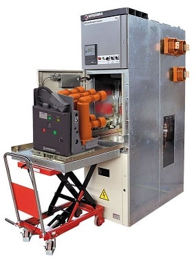
Outdoor metal-clad switchgear provides a weatherproof housing for circuit breakers, protective relays, meters, current transformers, potential transformers, bus conductors, and other items necessary to provide electric-system requirements.
Indoor switchgear must be installed in a building for protection from the elements.
For the typical 13.2–7.6 kV distribution substation, the switchgear consists of a 2,000A bus and six (6) breaker cells. The breaker cells are one 2,000A main breaker, four 1,200A feeder breakers, and one 2,000A future bus-tie breaker that will serve as the mobile sub connection. One of the feeder cells is equipped with a capacitor bank isolation switch.
Shunt Reactors
When the capacitive reactance from extra-high-voltage transmission-line circuits exceeds the ability of the system to absorb the reactive kVA (kiloVars), shunt reactors are installed.
A shunt reactor compensates for the shunt capacitance and the charging current drawn by a transmission line. In the absence of compensation for charging current, the voltage at the receiving end of a long transmission line can exceed the voltage at the sending end by as much as 50%.
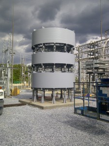
The shunt reactor is supported directly on a foundation.
The shunt reactor shown in the figure is a three-phase single-winding transformer. It serves as an inductive reactance on the power system, neutralizing capacitive reactance associated with the long extra-high-voltage transmission line.
Shunt reactors are usually located in substations and connected to a transmission line terminal through a disconnect switch.
Current-Limiting Inductor or Air Core Reactor
The purpose of a current-limiting inductor is to limit the amount of short-circuit current that can flow in a circuit by adding inductive reactance to it.
Dry inductors are typically used for current-limiting applications and do not usually include electromagnetic shielding. These inductors have a magnetic field surrounding them under normal conditions, which becomes stronger when they carry short-circuit current. The magnetic field of these inductors interacts with the field of other inductors when they are too close together. When metallic objects are placed in the magnetic field of an inductor, the magnetic field induces eddy currents. However, currents are induced in any closed conductive loops located within the inductor’s magnetic field.
To maintain the manufacturer’s recommended magnetic clearance and necessary personnel clearance, dry current-limiting inductors are usually supported on insulators and aluminum or fiberglass pedestals. The supporting pedestals are bolted directly to the foundation.
Line Trap
Line traps (also known as wave traps) present high impedance to carrier frequencies but negligible impedance to normal 60Hz or 50Hz line currents. It is a blocking filter that is used to restrict the carrier signal to the transmission line on which it is installed. This is done to prevent the carrier signal from entering substation equipment.
The line trap can be installed vertically or horizontally on either a single or multiple pedestal support structure. They have also been mounted with one end of the line trap supported by a coupling capacitor or coupling capacitor voltage transformer and the other end by an insulator. The line trap can also be suspended from a structure
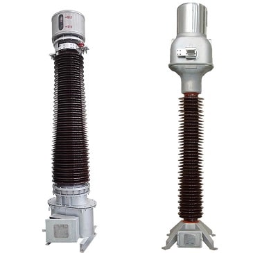
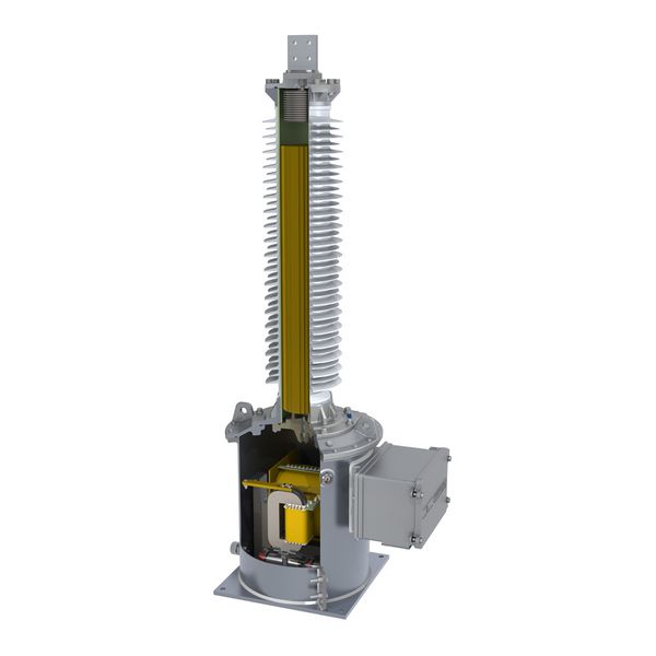
Coupling Capacitor Voltage Transformer
At voltages above about 100 kV (phase) the conventional electromagnetic type of potential transformer becomes expensive owing to insulation requirements. A less expensive alternative is Capacitive Voltage Transformer.
Communication signals in the form of high-frequency voltages are transmitted to the transmission lines through coupling capacitors.
Some of the coupling capacitors are equipped with potential devices which make it possible to measure the voltage on transmission-line circuits.
The coupling capacitor potential devices are accurate enough to be used for supplying voltages to protective relays but—unless they are specifically compensated —not accurate enough to supply voltages for meters designed for billing purposes.
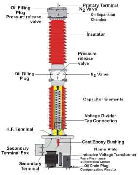
The figure above shows a coupling capacitor voltage transformer (CVT or CCVT).
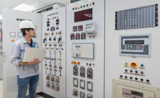
Control House
The substation control house is used to protect the control equipment, including switchboard panels, batteries, battery chargers, supervisory control, power-line carrier, meters, and relays, from the elements.
Underground and overhead conduits and control wire are installed to connect the controls of all the equipment in the substation to the control panels normally installed in the control house.
Each substation usually contains several thousand feet of conduit and miles of the control wire.
Control Panel
The control panels installed in a control house provide mountings for meters, relays, switches, indicating lights, and other control devices.
Substation Protective Relays
Substation protective relays installed on control panels are used to sense electrical failures on transmission and distribution circuits or in pieces of substation equipment, such as power transformers, substation bus, reactors, capacitors, and circuit breakers.
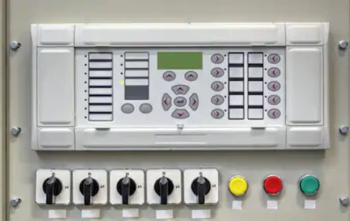
Some relays are used to supervise, monitor, and perform predetermined operations as required by system conditions.
Relays automatically operate their contacts to properly identify the source of trouble and remove it from the electrical system.
Protective relay systems provide overcurrent, differential current, overvoltage, under voltage, over frequency, under frequency, directional, and distance protection.
Supervisory Control
The supervisory control equipment permits the remote control of substations from a system control center or other selected point of control.
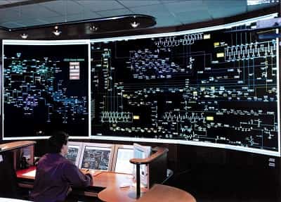
Distribution substations are normally unattended and operate automatically or are controlled remotely by supervisory control equipment from a central control center.
Supervisory control equipment is used to open and close circuit breakers, operate tap changers on power transformers, supervise the position and condition of equipment, and telemeter the quantity of energy flowing in a circuit or through a piece of equipment.
Remote Terminal Unit
The remote terminal unit (RTU) is the interface between the supervisory control and the substation equipment.
The RTU is a monitor and transmitter of the substation and electric system data.
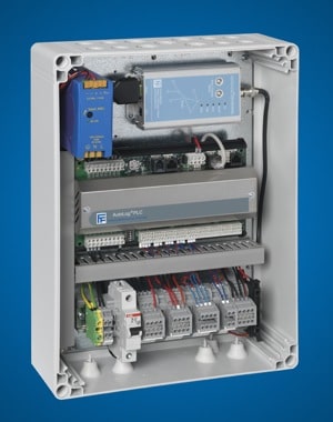
The Remote Terminal Unit (RTU), shall be installed at Substations to acquire analog data and digital data.
- Analog data includes KW export, KW import, frequency, OLTC, power factor, maximum demand, planned outage duration & numbers, forced outage duration & numbers, electricity consumed locally, MVA capacity of Sub-Station, length of Transmission lines, etc.
- Digital data include the status of isolators, circuit breakers, etc. at each Sub-Station under this scope of work and transfer those information to the data server at the supervisory control center and back-up supervisory control center.
Digital Fault Recorder
The digital fault recorder records fault data and provides an accurate sequence of events for system disturbances on the electric system.
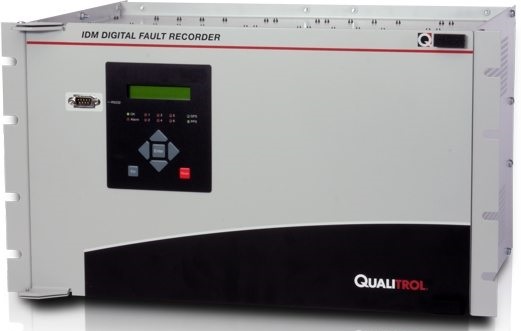
A digital fault recorder (DFR), is an IED that records information about power system disturbances. It is capable of storing data in a digital format when triggered by conditions detected on the power system.
Harmonics, frequency, and voltage are examples of data captured by DFRs.
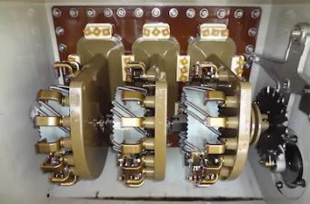
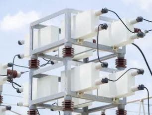
Capacitor Bank
Capacitor banks are used to maintain or increase voltages in power lines and reduce inductive losses, thereby improving efficiency of the power system.
After the capacitor bank is installed, the outer periphery of the bank should be enclosed inside a fence for protection of personnel, if electrical clearance is not provided.
Reactive kilovolt-amperes can be supplied to the electrical system by connecting banks of capacitors to the distribution circuits in substations or out on the distribution lines to neutralize the effect of customer-inductive loads.
Capacitors used in this manner help to control voltages supplied to the customer by eliminating the voltage drop in the system caused by inductive reactive loads.
Capacitors in distribution substations are usually mounted in metal cubicles. The capacitors, mounted on the racks in the cubicles, are usually single-phase, single-bushing units rated 100-kVAR through 400-kVAR capacitance, 60 Hz, and a voltage consistent with the distribution system.
They are connected between each of the three-phase conductors and ground. Capacitor units for the higher distribution voltages and those connected to conductors energized at transmission voltages are normally mounted on open-type racks.
The capacitor units are connected in series and cascaded to provide equipment that can be connected to the higher voltage distribution and transmission systems.
Voltage Regulator
The voltage regulators maintain the system voltage on the distribution circuits. As settings on the voltage regulators are adjusted for various load conditions that occur, the desired voltage is obtained.
Power-Line Carrier Equipment
The power-line carrier equipment provides high-frequency voltages to be used for transmitting voice communications or telemetered signals on high-voltage transmission-line circuits.
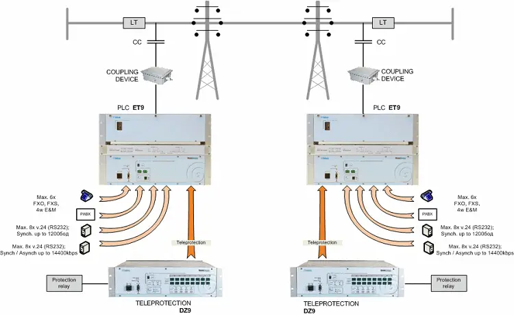
In the case of voice communications, the sound frequency modulates a high-frequency signal connected to the transmission-line circuit using coupling capacitors.
This equipment permits using the line conductors for communication, relaying, supervisory control, and metering in addition to the transmission of electric power.
Microwave Equipment
Radio signals used for point-to-point communications between substations or other power-system facilities operating in the megahertz frequencies are called microwave.
The frequencies range from 952 MHz to 13,000 MHz or higher. Microwave radio signals are used for communication channels, protective relaying, supervisory control, and remote metering.
Batteries
Control batteries supply energy to operate circuit breakers and other equipment.
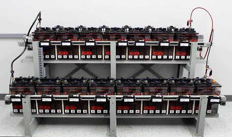
It is necessary to use dc control systems with a storage battery as a source to make it possible to operate equipment during periods of system disturbances and outage.
Battery chargers are used to automatically keep the batteries charged completely to provide sufficient emergency power for all necessary operations.