• Home
  • Courses
  • Machines
    • Transformer
    • AC Motors
      • Induction Motor
      • Synchronous Motor
    • DC Motor
    • DC Generator
  • Power System
    • Circuit Breaker
    • Switchgear
    • Substation
    • Control System
    • Measurement
  • Electronics
  • Blog
  • Contact
    • Contact Us
    • Privacy Policy
Have any question?
[email protected]
RegisterLogin
StudyElectrical.Com
  • Home
  • Courses
  • Machines
    • Transformer
    • AC Motors
      • Induction Motor
      • Synchronous Motor
    • DC Motor
    • DC Generator
  • Power System
    • Circuit Breaker
    • Switchgear
    • Substation
    • Control System
    • Measurement
  • Electronics
  • Blog
  • Contact
    • Contact Us
    • Privacy Policy

Substation

Lightning Arrester – Location, Rating and Selection

  • Categories Substation, Power System

A lightning arrester is connected to protect a piece of equipment from lightning and switching surges.

Overvoltages may cause the burning of insulation of substation equipment if not well protected. Lightning is one of the most serious causes of overvoltages. 

There are various types of lightning arrester construction. They are 

  1. Rod gap LA
  2. Expulsion type LA
  3. Valve type LA
  4. Horn gap LA
  5. Pellet type LA
  6. Thyrite type LA, etc.


An ideal Lightning Arrester should possess the following characteristics.
  • It  must not take any current at normal system voltage
  • Any transient wave with a voltage peak exceeding the spark over voltage must cause it to break down.
  • After the breakdown, it must be capable of carrying the resulting discharge current without any damage to itself and without voltage across it exceeding the breakdown voltage.
  • The power frequency current following the breakdown must be interrupted as soon as the transient voltage has fallen below the breakdown value.

Table of Contents

  • Location of Lightning Arrester
  • Lightning Arrester Ratings
  • Selection of LA
    • Related Articles

Location of Lightning Arrester

Lightning arrester should be located close to the equipment that it is expected to protect.

Lightning Arrester
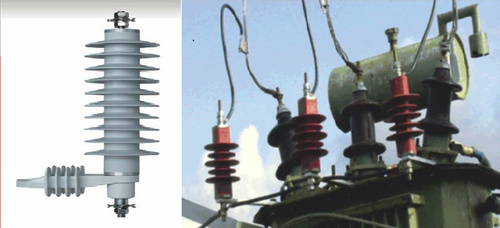
Lightning Arrester on a Transformer

In large substations, arrestors should be installed at take-off points of the lines and of the terminal apparatus.

Many factors like system voltages, basic impulse insulation level, arrestor rating, station layout, number and arrangement of lines, the position of isolators, the distance between equipment, etc. have to be taken into account in fixing the location of the arrestors. 

The length of the arrester lead should be as low as possible and should not exceed 10M.

The Arresters are installed both on the High Voltage and Low Voltage side of the transformers. Junction of an OH line and the cable should be protected by LA. Separate earth should be provided for each LAs. LA ground leads should not be connected to the station earth bus.

Lightning Arrester Ratings

The rating of a lightning arrester is given below,
  1. Normal or rated voltage: It is designated by the maximum permissible value of power frequency voltage which it can support across its line and earth terminal while still carrying effectively and without the automatic extinction of the follow-up current. The voltage rating of the arresters should be greater than the maximum sound phase to ground voltage.
  2. Normal Discharge current: It is the surge current that flows through the LA after the spark over, expressed in crest value (peak value) for a specified wave shape. Example 10, 5, 2.5, 1.5, 1 kA rating.
  3. Power frequency spark over voltage: It is the RMS value of the power frequency voltage applied between the line and earth terminals of the arrester and earth which causes spark over of the series gap. As per IS 3070, the recommended spark overvoltage is 1.5 times the rated voltage.
There are also other ratings like maximum impulse spark over-voltage, residual or discharge voltage, maximum discharge current, etc.

Selection of LA

Here we are selecting an appropriate rating of lightning arresters for the substation.

For the protection of substation above 66kV, an arrester of 10kA rating is used.

Voltage rating of LA = Line to line voltage × 1.1 × coefficient of earthing.

Power frequency spark over voltage = 1.5 ×Voltage rating of LA

(Assuming coefficient of earthing equals 0.8 for the effectively earthed system)

For 220KV side:

Voltage rating = 1.1 × 220 × 0.8 = 193.6KV
Power frequency spark over voltage = 1.5 ×193.6 = 290.4KV
Rated discharge current = 10 kA

For 110KV side:

Voltage rating = 1.1 × 110×0.8 = 96.8KV
Power frequency spark over voltage = 1.5 × 96.8 = 145.2KV
Rated discharge current  = 10kA

For 66kV Side 

Voltage rating = 1.1 × 66×0.8 = 58.08kV
Power frequency spark over voltage = 1.5 × 58.08 = 87.12kV
Rated discharge current = 10kA

For 11 KV side:

Voltage rating = 1.1× 11×0.8 = 9.68KV
Power frequency spark over voltage = 1.5×9.68 = 14.52KV
Nominal discharge current = 5kA

Related Articles

  • surge
    Voltage Surge in Power System

    What is Voltage Surge or Transient Voltage? The sudden rise in voltage for a very…

  • Types of Power plants
    Types of Power Plants

    What is the Power Plant? A power plant is an assembly of systems or subsystems…

  • protective zones in power system
    Protective Zones in Power Systems

    In this post, we will look into protective zones in the power system and why…

  • dc motor voltage and power equations
    Voltage and Power Equations of DC Motor | Condition of Maximum Power

    In this post, we will look at the voltage and power equation of a dc…

  • Gas turbine power plant
    Introduction to Gas Turbine Power Plant

    The gas turbine power plant obtains its power by utilizing the energy of burnt gases…

  • fUNCTION OF PROTECTIVE RELAYS
    Function of Protective Relays in Power System

    We usually think of an electric power system in terms of its more impressive parts…

  • Share:
author avatar
Electrical Engineer

Previous post

Transformer Oil Filtration and Hot Oil Circulation Process
June 23, 2014

Next post

Circuit Breaker Ratings
June 24, 2014

You may also like

percentage_reactance transformer
Percentage Reactance in Power System (Transformer, Generator or Reactor)
16 January, 2023
Load Curve and Load Duration Curve
Load Duration Curve in Power Station
29 September, 2022
Double end break disconnect switch
Disconnect Switches (Isolator) in Substation: Types, Design and Working
1 September, 2022

    7 Comments

  1. Shadik
    March 26, 2019
    Reply

    I have read that, voltage rating of LA = Line voltage x √2 / √3 , But here you have shown the formulae is different, Could you please tell me which one is correct.

    • manojkumar
      October 30, 2019
      Reply

      yes ofcourse: root 2 ÷ root 3 = 0.81
      and v rating of LA = 1.1*0.8*line voltage
      but hear the question is why 1.1 taken.

      • NAMAN SHARMA
        July 28, 2020
        Reply

        1.1 is 10% of Marginal factor which is taken for every protective equipment.

  2. Zulfiqar
    March 1, 2020
    Reply

    Very interesting knowledge of my life

  3. Kalaiselvan P
    April 25, 2020
    Reply

    Dear sir
    How we are calculating Rated discharge current = 10kA for 220,110,66kv and for 11kv as 5kA

Leave A Reply Cancel reply

Your email address will not be published. Required fields are marked *

Search Here

From Blog

Synchronous 2Bmotor 2Bstarting 2Bmethods
Starting Methods for Synchronous Motor
19Nov2018
Slip ring Construction
Slip Rings and Their Connection to Modern Engineering
28Jul2022
Electric current concept
Concept of Electric Charge and Current
22Dec2021
AB-Switch
Air Break Switch – Types and Uses
08Sep2015

Categories

  • Alternator
  • Arduino
  • Basic Electrical
  • Battery
  • Books
  • Cables
  • Capacitor
  • Career
  • Circuit Breaker
  • Control System
  • DC Generator
  • DC Motor
  • Drives
  • Electric Vehicles
  • Electrical Circuits
  • Electrical Machines
  • Electrical Relays
  • Electrical Safety
  • Electronics
  • Embedded System
  • Exams
  • Generation
  • Guest Post
  • HVDC
  • Instrumentation
  • Interview Questions
  • Locomotives
  • Measurement
  • Microcontroller
  • Objective Questions
  • PCB
  • PLC
  • Power System
  • Problems and Solution
  • Projects
  • Resistor
  • Signals and Systems
  • Single Phase Motors
  • Substation
  • Switchgear
  • Synchronous Motor
  • Three Phase Induction Motor
  • Transformer
  • Transmission Line
  • Uncategorized

Copyright © 2021 Study Electrical, Inc.

© StudyElectrical.Com 2021

Login with your site account

Lost your password?

Not a member yet? Register now

Register a new account

Are you a member? Login now