Capacitor Voltage Transformer (CVT) or Capacitor Coupled Voltage Transformer (CCVT) is a switchgear device used to convert high transmission class voltage into easily measurable values, which are used for metering, protection, and control of high voltage systems.
Additionally, a CVT/CCVT used as coupling capacitors for coupling high-frequency power line carrier signals to the transmission line.
The capacitor voltage transformer (CVT) is used for line voltmeters, synchroscopes, protective relays, tariff meter, etc. A voltage transformer VT is a transformer used in power systems to step down extra high voltage signals and provide a low voltage signal, for measurement or to operate a protective relay.
The performance of a Capacitor Voltage Transformer (CVT) or Capacitor Coupled Voltage Transformer (CCVT) is inferior to that of the electromagnetic voltage transformer. Its performance is affected by the supply frequency, switching transients, the magnitude of connected burden, etc.
The capacitor voltage transformer is more economical than an electromagnetic voltage transformer when the nominal system voltage increases above 66 kV.
The carrier current equipment can be connected via the capacitor of the Capacitor Voltage Transformers. Thereby there is no need for separate coupling capacitors.
Capacitor Voltage Transformers also serve as coupling capacitors for coupling high-frequency power line carrier signals to the transmission line.
CVTs in combination with wave traps are used for filtering high-frequency communication signals from power frequency. This forms a carrier communication network throughout the transmission network.
Capacitor type VT is used for voltages 66 kV and above. At such voltages cost of the electromagnetic type, VT’s tends to be too high.
Working of Capacitor Voltage Transformer (CVT/CCVT)
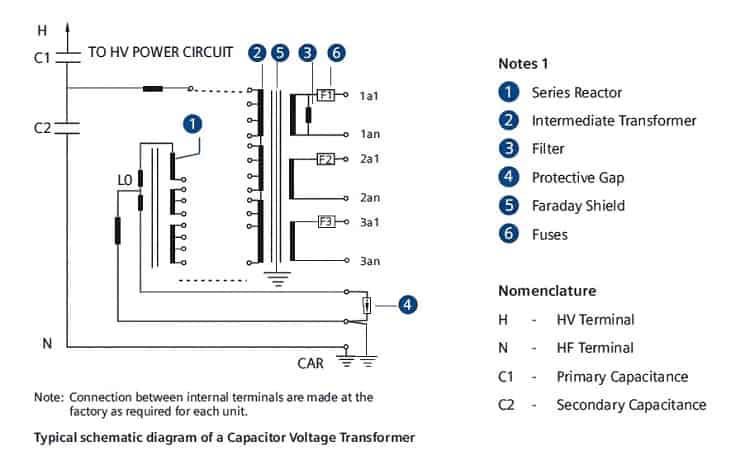
The capacitors connected in series act like potential dividers provided the current taken by the burden is negligible compared with the current passing through the series-connected capacitors.
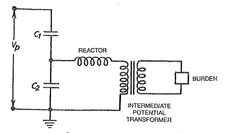
However, the burden current becomes relatively larger and ratio error and also phase error is introduced. Compensation is carried out by ‘tuning’.
The reactor connected in series with the burden is adjusted to such a value that at supply frequency it resonates with the sum of two capacitors. This eliminates the error.
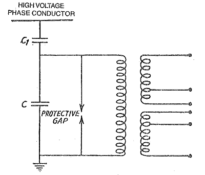
The construction of capacitor type VT depends on the form of a capacitor voltage divider. Generally, high voltage capacitors are enclosed in a porcelain housing. A large metal sheet box at the base encloses the tuning coil intermediate transformer.
In an electrical power substation, Capacitor Voltage Transformer in combination with Wave Trap is placed at the sending and receiving ends of the substation. At the receiving end, they are found just after lightning arrester and before line isolator.
Construction of Capacitor Voltage Transformer (CCVT)
Capacitor Voltage Transformer consists of two primary assemblies,
- the high voltage capacitor sections, and
- the base box, housing the electromagnetic components.
The general arrangement of a CCVT is given below,
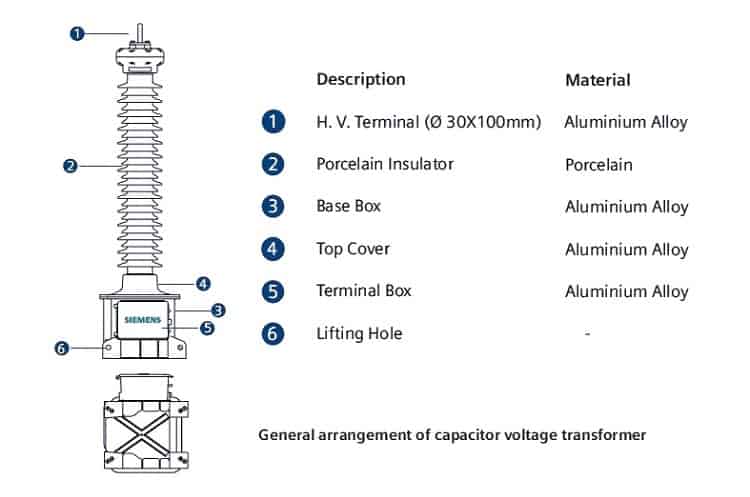
Capacitor voltage transformer isolates the measuring instruments, meter, relays, protections, etc., from the high voltage power circuit and provide a scaled replica of the voltage in the HV line. Coupling Capacitors are only used for coupling high-frequency communication signals and they are equivalent to the capacitive part of CVT.
Each capacitor section is equipped with stainless steel below which will allow the synthetic fluid to expand and contract with changes in ambient operating temperature while maintaining the hermetic sealing. It is over these capacitor sections that most of the high voltage will be dropped.
The main applications of CVT in High Voltage Networks ( above 36 kV ) are given below. Tap voltage (approximately 5-12 kV depending on the type) is taken from the lowest capacitor section and fed to an electromagnetic circuit in the cast aluminum base box.
Design of Capacitor Voltage Transformer
The base box contains the intermediate transformer which will provide the final output voltages via multiple tapped secondary windings, series compensating reactor and Ferro-resonance control circuitry. The base box is filled with dried mineral oil, protecting the components from environmental deterioration.
Ferro-resonance is simply and effectively controlled by the utilization of low flux density designed magnetic circuitry and a saturable reactor controlled damping circuit connected across the secondary winding. The Ferro-resonance suppression circuit does not adversely affect the transient response.

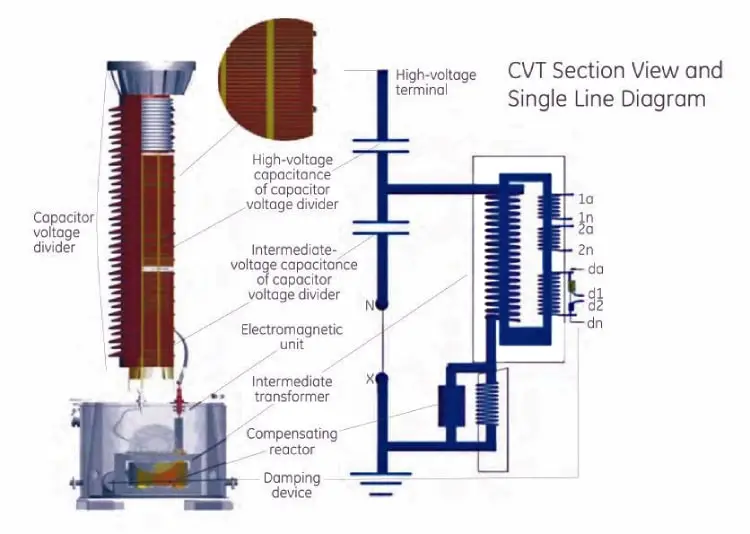
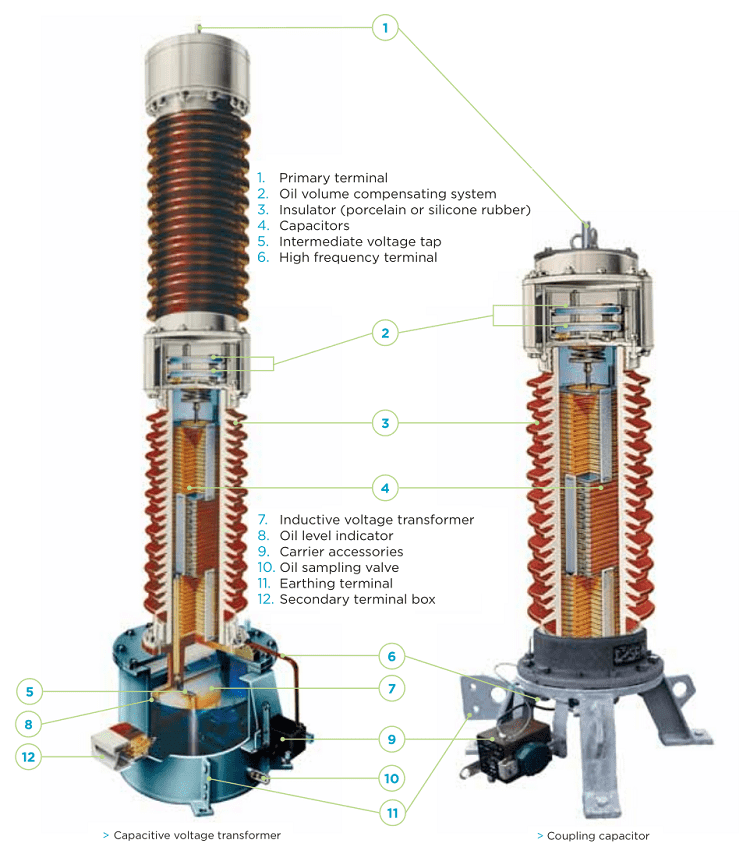
Capacitor voltage transformer consists of a series of capacitors connected in series on top of a tank. The electromagnetic unit is inside the tank.
The electromagnetic unit consists of an
- inductive transformer(5),
- a series reactor(8) and
- auxiliary elements.
These capacitors form a voltage divider (2, 3) between the high voltage terminal (1) and the high-frequency terminal (4).
The capacitors, impregnated with high-grade dielectric oil, are housed in one or more insulators. Each of them forms a hermetically sealed independent unit, with a very stable capacitance over time.
The high-frequency terminal (4) for the PLC signal comes out of one side through a piece of resin that separates the capacitive unit from the inductive voltage transformer.
The medium voltage inductive voltage transformer is immersed in mineral oil and housed inside a hermetically sealed metallic tank.
The secondary terminals are located inside a box (7) enabling connections and has space with protection elements such as fuses or circuit breakers.
Applications of CVT
Some of the important applications of CVT are:
- Voltage Measuring: They accurately transform transmission voltages down to useable levels for revenue metering, protection and control purposes.
- Insulation: They guarantee the insulation between the HV network and LV circuits ensuring safety condition to control room operators.
- HF Transmissions: They can be used for Power Line Carrier (PLC) coupling.
- Transient Recovery Voltage: When installing in close proximity to HV/EHV Circuit Breakers, CVT’s own High Capacitance enhance C/B short line fault / TRV performance.
Example of Applications
Some of the examples of the application of CVT (Capacitor Coupled Voltage Transformer) are,
- Revenue metering.
- Protection for high voltage lines and substations.
- Transmission of high-frequency signals.