A current transformer (CT) is a type of transformer that is used to measure AC current. It produces an alternating current (AC) in its secondary which is proportional to the AC current in its primary. Current transformers, along with voltage or potential transformers are Instrument transformer.
Current transformers are designed to provide a scaled-down replica of the current in the HV line and isolate the measuring instruments, meters, relays, etc., from the high voltage
power circuit.
The large alternating currents which can not be sensed or passed through the normal ammeter, and current coils of wattmeters, energy meters can easily be measured by use of current transformers along with normal low range instruments.
Related: Working Principle of Transformer
Current Transformer Symbol / Circuit Diagram

A current transformer (CT) basically has a primary coil of one or more turns of heavy cross-sectional area. In some, the bar carrying high current may act as a primary. This is connected in series with the line carrying high current.

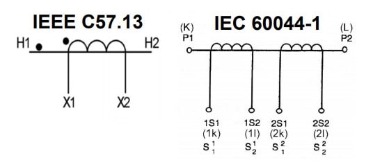
The secondary of the current transformer is made up of a large number of turns of fine wire having a small cross-sectional area. This is usually rated for 5A. This is connected to the coil of normal range ammeter.
Related: Why Current Transformer (CT) Secondary Should not be Open ?
Working Principle of Current Transformer
These transformers are basically step-up transformers i.e. stepping up a voltage from primary to secondary. Thus the current reduces from primary to secondary.
Let,
N1 = Number of Primary Turns
N2 = Number of Secondary Turns
I1 = Primary Current
I2 = Secondary Current
For a transformer,
I1/I2 = N2/N1
As N2 is very high compared to N1, the ratio I1 to I2 is also very high for current transformers. Such a current ratio is indicated for representing the range of the current transformer.
For example, consider a 500:5 range then it indicates that C.T. steps down the current from primary to secondary by a ratio 500 to 5.
I1/I2 = 500/5
Knowing this current ratio and the meter reading on the secondary, the actual high line current flowing through the primary can be obtained.
Types of Current Transformer
On the basis of their applications in the field, current transformers can be broadly classified into two types,
- Indoor current transformers
- Outdoor current transformers
Indoor Current Transformers
Current transformers designed for mounting inside metal cubicles are known as Indoor Current Transformers.
Depending upon the method of insulation, these can further be classified as:
- Tape insulated
- Cast resin (epoxy, polyurethane or polycrete)
In terms of constructional aspects, Indoor Current Transformers can be further classified into the following types:
- Bar Type CT: The CTs having a bar of suitable size and material used as primary winding are known as bar-type CT s’. The bar may be of rectangular or circular cross-section.
- Slot/ Window/ Ring Type CT: CTs having an opening in the center to accommodate a primary conductor through it is known as ‘ring-type’ (or ’slot/ window type’) CT.
- Wound Type CT: A CT having a primary winding of more than one full turn wound on the core is known as wound type CT. The connecting primary terminals may be similar to those of a bar type CT or rectangular pads can be provided for this purpose.
Outdoor Current Transformer
These current transformers are designed for outdoor application. They use transformer oil or any other suitable liquid for insulation and cooling. A liquid-immersed CT which is sealed and does not communicate with the atmosphere is known as a hermetically sealed CT.
Outdoor oil-filled CTs are further classified as
- live tank type CT
- dead tank type CT
Most of the outdoor current transformers are high voltage current transformers. Based on the application they are further classified into :
- Measurement Current Transformer
- Protection Current Transformer
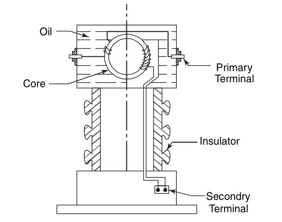
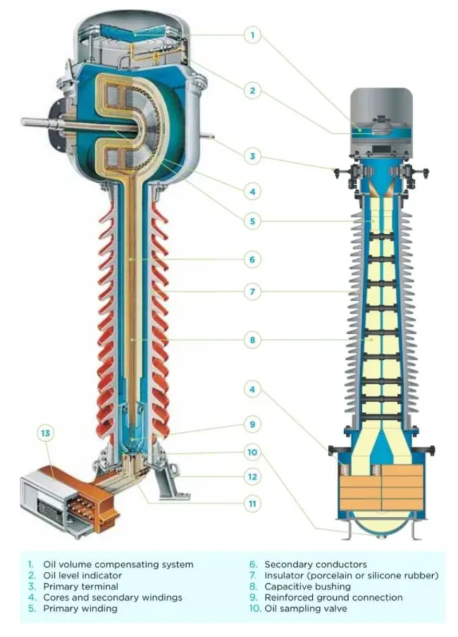
Live Tank Current Transformer
In this design of instrument transformers, the tank housing the cores is kept at the system voltage. A live tank CT is shown in the figure. It can be noted that the bushing of this CT is prone to damages in transit as its center of gravity is at large height.
Dead Tank Current Transformer
In Dead Tank design of current transformers, the tank housing the cores is kept at earth potential.
The figure shows a dead tank (single bushing) design which is mounting wise similar to a live tank design but here the center of gravity is low. Hence this type of CT is not damaged in transit.
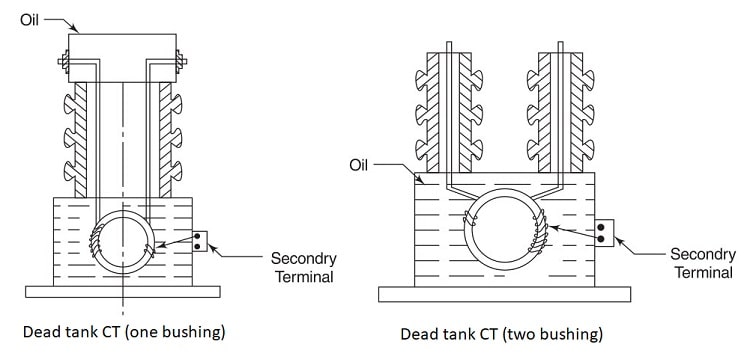
The figure depicts dead tank CT (two-bushing) which is very compact in size and can be mounted on a steel structure near the outdoor circuit breakers.
A CT having more than one core and more than one secondary winding is known as a multi-core CT (for example, a CT having metering and protection cores).
A CT in which more than one ratio is obtainable by reconnection or tapings in primary or secondary windings is known as a multi-ratio instrument transformer (e.g. a CT having a ratio of 800-400-200/1 A). In such transformers, tapings in primary windings must be avoided as far as permitted by the design.
An instrument transformer intended to serve the dual purpose of measuring and protection is known as a dual-purpose instrument transformer.
A CT having a split metering core used for the measurement of current in a busbar is known as a split-core CT. The spring action of a split-core CT allows the operator to use this CT for enveloping a current-carrying low tension busbar, without stopping the current flow.
Measurement CT and Protection CT
A CT is similar to a power transformer to some extent since both depend on the same fundamental mechanism of electromagnetic induction but there are considerable differences in their design and operation.
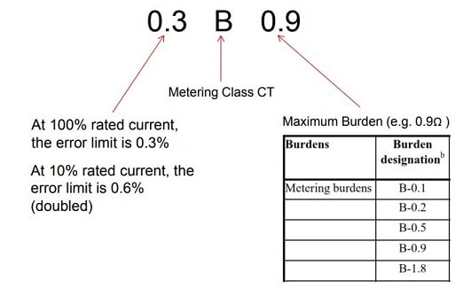
Current Transformer used for metering and indicating circuits are popularly termed as Measuring CT.
Current Transformer used in conjunction with protective devices is termed as Protection CT.
A measurement grade CT has much lower VA capacity than a protection grade CT. A measurement CT has to be accurate over its complete range e.g. from 5% to 125% of normal current. In other words, its magnetizing impedance at low current levels (and hence low flux levels) should be very high.
A metering core CT is designed to work more accurately within the rated current range designated. When current flow exceeds that rating, the metering core will become saturated, thereby limiting the amount of current level within the device. This protects connected metering devices from overloading in the presence of fault level current flows. It buffers the meter from experiencing excessive torques that might be created during those faults.
In contrast, for a protection grade CT, the linear response is expected up to 20 times the rated current. Its performance has to be accurate in the range of normal currents and up to fault currents. Specifically, for protection grade current transformers, magnetizing impedance should be maintained to a large value in the range of the currents of the order of fault currents.
A protection core is designed to transform a distortion-free signal even well into the overcurrent range. This enables the protective relays to measure the fault current value accurately, even in very high current conditions.
For measuring CTs, the accuracy required is within the normal working range of up to 125 percent of the rated current. For over-current conditions beyond this, accuracy is not desired, rather there must be saturation in the core to relieve the connected instruments of the stresses due to over-current.
Accuracy is not required for currents below the rated Value for protection CTs. But there must be accuracy at all higher values of current up to a maximum primary current equal to the maximum system fault level.
The decision as to whether or not to use dual-purpose CT for measuring and protection depends on various factors such as design, cost and space as also on the ability of the instrument to withstand short time over-current.
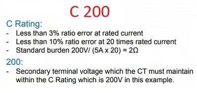
Class T and Class C Current Transformers
ANSI/IEEE standards classify CTs into two types:
- Class T Current Transformer
- Class C Current Transformer
Typically, a class T CT is a wound type CT with one or more primary turns wound on a core. It is associated with high leakage flux in the core. Because of this, the only way to determine it’s performance is by test. In other words, standardized performance curves cannot be used with these types of CTs.
For class C CT, letter designation ‘C’ indicates that the leakage flux is negligible. Class C CTs are the more accurate bar type CTs. In such CTs, the leakage flux from the core is kept very small. For such CTs, the performance can be evaluated from the standard exciting curves. Also, the ratio error is maintained within ±10% for standard operating conditions.
Construction of Current Transformer
As we discussed above, there are three types of constructions used for the indoor current transformers which are,
- Wound Type CT
- Toroidal (Window) Type CT
- Bar Type CT
Wound Type Current Transformer – The transformers primary winding is physically connected in series with the conductor that carries the measured current flowing in the circuit. The magnitude of the secondary current is dependent on the turn’s ratio of the transformer.
 Type CT Bar Type CT")
Bar-type Current Transformer – This type of current transformer uses the actual cable or bus-bar of the main circuit as the primary winding, which is equivalent to a single turn. They are fully insulated from the high operating voltage of the system and are usually bolted to the current-carrying device.
1. Wound Type Current Transformer
In wound type construction the primary is wound for more than one full turn on the core.

The construction of Wound Type Current Transformer is shown above.
In a low voltage wound type current transformer, the secondary winding is wound on a bakelite former. The heavy primary winding is directly wound on the top of the secondary winding with suitable insulation in between the two.
Otherwise, the primary is wound completely separately and then taped with suitable insulating material and assembled with the secondary on the core.
The current transformers can be ring type or window type. Some commonly used shapes for the stampings of window type current transformers are shown in the figure below.
The core material for wound type is nickel-iron alloy or oriented electrical steel. Before installing the secondary winding on the core it is insulated with the help of end collars and circumferential wraps of pressboards. Such pressboards provide additional insulation and protection to the winding from damage due to the sharp corners.
2. Bar Type Current Transformer

The stampings used for the laminations in current transformers must have high cross-sectional area than the ordinary transformers. Due to this, the reluctance of the interleaved comers remains as low as possible. Hence the corresponding magnetizing current is also small.
The windings are placed very close to each other so as to reduce the leakage reactance. To avoid the corona effect, in bar type transformer, the external diameter of the tube is kept large.
The windings are so designed that without damage, they can withstand short circuit forces which may be caused due to a short circuit in the circuit in which the current transformer is inserted.
For small line voltages, the tape and varnish are used for insulation. For line voltages above 7 kV, the oil-immersed or compound filled current transformers are used.
Uses / Advantages of Current Transformer
Current transformers are used extensively for measuring current and monitoring the operation of the power grid.

Along with voltage leads, revenue-grade current transformers drive the electrical utility’s watt-hour meter on virtually every building with three-phase service and single-phase services greater than 200 amperes.
High-voltage current transformers are mounted on porcelain or polymer insulators to isolate them from the ground.
Current transformers can be mounted on the low voltage or high voltage leads of a power transformer.
Often, multiple CTs are installed as a “stack” for various uses. For example, protection devices and revenue metering may use separate CTs to provide isolation between metering and protection circuits and allows current transformers with different characteristics (accuracy, overload performance) to be used for the devices.
Application of High Voltage Current Transformers
Ideal for installation at metering points due to its very high accuracy.
Excellent frequency response; ideal for monitoring power quality and measuring harmonics.
Suitable for installation in AC and DC filters in converter substations for HVDC projects.
Examples of applications:
- Protection for high voltage lines and substation.
- Protection for capacitor banks.
- Protection for power transformers.
- Revenue metering.