• Home
  • Courses
  • Machines
    • Transformer
    • AC Motors
      • Induction Motor
      • Synchronous Motor
    • DC Motor
    • DC Generator
  • Power System
    • Circuit Breaker
    • Switchgear
    • Substation
    • Control System
    • Measurement
  • Electronics
  • Blog
  • Contact
    • Contact Us
    • Privacy Policy
Have any question?
[email protected]
Login
StudyElectrical.Com
  • Home
  • Courses
  • Machines
    • Transformer
    • AC Motors
      • Induction Motor
      • Synchronous Motor
    • DC Motor
    • DC Generator
  • Power System
    • Circuit Breaker
    • Switchgear
    • Substation
    • Control System
    • Measurement
  • Electronics
  • Blog
  • Contact
    • Contact Us
    • Privacy Policy

    Circuit Breaker

    Circuit Breaker Definition, Working Principle and Arcing Phenomenon

    • Categories Circuit Breaker, Substation, Switchgear
    Circuit-Breaker-Working-Principle.gif

    Table of Contents

    • Definition
    • Circuit Breaker Working Principle
    • Arcing Phenomenon in Circuit Breaker
    • Methods of Arc Extinction in Circuit Breaker
      • High Resistance Method
      • Types of Circuit Breaker
      • Related Articles

    Definition

    A circuit breaker means the device which breaks (Open) the circuit under the abnormal condition and protects the system from hazards.

    The function of a circuit breaker is to isolate the faulty point of the power system in case of abnormal conditions such as faults.

    Keep reading to understand the working principle of the circuit breaker.

    Different types of circuit breakers are used to perform this function. There are low voltage circuit breakers and high voltage circuit breakers. High voltage circuit breakers are mainly used in substation and low voltage CB are used in home circuits.

    Important high voltage circuit breakers used in the electrical substation are

    • SF6 Circuit breaker and
    • Vacuum Circuit breaker.

    Low voltage CB includes

    • Miniature Circuit breaker (MCB),
    • Molded Case Circuit Breaker (MCCB),
    • Residual Current Circuit breaker (RCCB) or
    • Ground Fault Circuit Interrupter (GFCI)

    A protective relay is another important device in the power system switchgear. Relay detects abnormal conditions and sends a tripping signal to the circuit breaker. After receiving the tripping command from the relay, the circuit breaker isolates the faulty part from the power system.

    A circuit breaker essentially consists of fixed and moving contacts, called electrodes.  These contacts are placed in the closed chamber containing a fluid containing medium (either liquid or gas) which quenches the arc formed between the contacts. 

    Under normal operating conditions, these contacts remain closed and will not open automatically until and unless the system becomes faulty.

    The contacts can be opened manually or by remote control whenever desired.

    When a fault occurs on any part of the system, the trip coils of the breaker get energized. The moving contacts are pulled apart by some mechanism, thus opening the circuit.

    Circuit Breaker Working Principle

    The working principle of the circuit breaker is explained in this section.

    When the contacts of a circuit breaker are separated under fault conditions, an arc is struck between them. The current is thus able to continue until the discharge ceases.
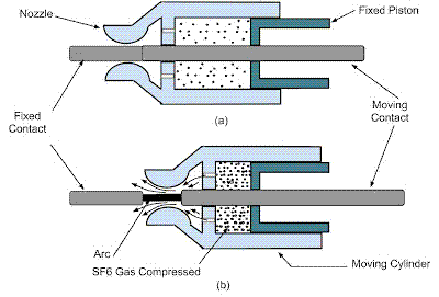
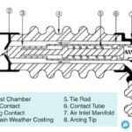
    Working of an SF6 Circuit Breaker
    Working of an SF6 Circuit Breaker

    The production of arc not only delays the current interruption process but it also generates enormous heat. This heat may cause damage to the system or to the breaker itself.

    Therefore, the main problem in a circuit breaker is to extinguish the arc within the shortest possible time. So that heat generated by it may not reach a dangerous value.

    Arcing Phenomenon in Circuit Breaker

    When a short-circuit occurs, a heavy current flows through the contacts of the circuit breaker before they are opened by the protective system.

    At the instant when the contacts begin to separate the contact area decreases rapidly. Also, a large fault current causes increased current density and hence rise in temperature.

    The heat produced in the medium between contacts (usually the medium is oil or air) is sufficient to ionize the air or vaporize and ionize the oil. The ionized air or vapor acts as a conductor and an arc is struck between the contact.

    The potential difference between the contacts is quite small and is just sufficient to maintain the arc. The arc provides a low resistance path and consequently, the current in the circuit remains uninterrupted so long as the arc persists.

    During the arcing period, the current flowing between the contacts depends upon the arc resistance. The greater the arc resistance, the smaller the current that flows between the contacts.

    The arc resistance depends upon the following factors:

    The degree of ionization – the arc resistance increases with the decrease in the number of ionized particles between the contacts.

    Length of the arc – the arc resistance increases with the length of the arc i.e. separation of contacts.

    Cross-section of arc – the arc resistance increase with the decrease in the area of cross-section of the arc.

    Methods of Arc Extinction in Circuit Breaker

    There are two methods of extinguishing the arc in circuit breakers

    1. High resistance method
    2. Low resistance or current zero method.

    High Resistance Method

    In the High resistance method, arc resistance is made to increase with time so that current is reduced to a value insufficient to maintain the arc. Consequently, the current is interrupted or the arc is extinguished.

    The principal disadvantage of high resistance method is that enormous energy is dissipated in the arc. Therefore, it is employed only in DC circuit breakers and low-capacity AC circuit breakers.

    Low Resistance or Current Zero Method

    Current zero method is employed for arc extinction in AC Circuits only.

    In this method, arc resistance is kept low until the current zero where the arc extinguishes naturally and is prevented from restriking in spite of the rising voltage across the contacts.

    All modern high power AC Circuit Breakers employ this method for arc extinction.

    Types of Circuit Breaker

    The basic types of circuit breakers according to the medium of arc interruption are

      1. Oil circuit breaker.
      2. Air Blast circuit breaker.
      3. SF6 circuit breaker.
      4. Vacuum circuit breaker

    Related Articles

    • interview question circuit breaker
      Circuit Breakers - Interview Questions with Answers

      1. What is a Circuit Breaker? Circuit Breaker is a mechanical device designed to close…

    • Sulphur Hexafluoride SF6 Circuit Breakers Construction Working and Advantages
      SF6 Circuit Breakers - Construction, Types and Working

      In an SF6 Circuit breaker, sulphur hexafluoride gas is used as the arc quenching medium. The…

    • Construction of Air Blast Circuit Breaker Interrupter
      Air Blast Circuit Breaker - Construction, Working and Types

      Air blast circuit breaker employs a high-pressure air blast as an arc quenching medium. The…

    • indoor-vacuum-circuit-breaker
      Vacuum Circuit Breaker (VCB) - Principle, Construction and Working

      What is VCB? VCB stands for Vacuum Circuit Breaker. In vacuum circuit breakers, the vacuum…

    • circuit breaker rating
      Circuit Breaker Ratings

      The rating of circuit breaker is given according to the duties that are performed by…

    • ACB Air Circuit Breaker
      Working of Air Circuit Breakers

      What is an ACB? A circuit breaker in which the contacts open and close in…

    • Share:
    author avatar
    Electrical Engineer

    Previous post

    What is an HVDC (High Voltage Direct Current) Transmission System?
    December 8, 2018

    Next post

    Types of Underground Cables
    December 11, 2018

    You may also like

    Equivalent Circuit for Tan δ Measurement and Phasor Diagram
    Tan Delta Test | Loss Angle Test | Dissipation Factor Test
    9 May, 2023
    pin-insulator (1)
    Pin Type Insulators: Construction, Working and Application
    7 May, 2023
    Transformer testing at factory
    Percentage Reactance in Power System (Transformer, Generator or Reactor)
    16 January, 2023

      6 Comments

    Leave A Reply Cancel reply

    Your email address will not be published. Required fields are marked *

    Search Here

    From Blog

    electrical exams
    5 Tips for Preparing for an Electrical Exam
    20Feb2023
    Build a simple dc motor at home
    How to Make a DC Motor at Home?
    13Sep2016
    Residential Electrical Wiring - 3 Surprising Dangers
    Maintaining Residential Electrical Wiring – 3 Surprising Dangers to Look out For
    06Sep2022
    Type B MCB
    Type B Miniature Circuit Breaker ( Type B MCB)
    09Apr2020

    Categories

    • Alternator
    • Arduino
    • Basic Electrical
    • Battery
    • Books
    • Cables
    • Capacitor
    • Career
    • Circuit Breaker
    • Control System
    • DC Generator
    • DC Generator MCQ
    • DC Generator Solved Problems
    • DC Motor
    • DC Motor MCQ
    • Drives
    • Electric Vehicles
    • Electrical Circuits
    • Electrical Machines
    • Electrical Relays
    • Electrical Safety
    • Electronics
    • Embedded System
    • Exams
    • Generation
    • Guest Post
    • HVDC
    • Instrumentation
    • Interview Questions
    • Locomotives
    • MCQ
    • Measurement
    • Microcontroller
    • Objective Questions
    • PCB
    • PLC
    • Power System
    • Problems and Solution
    • Projects
    • Resistor
    • Signals and Systems
    • Single Phase Motors
    • Substation
    • Switchgear
    • Synchronous Motor
    • Three Phase Induction Motor
    • Transformer
    • Transmission Line
    • Uncategorized

    Copyright © 2021 Study Electrical, Inc.

    © StudyElectrical.Com 2021

    Login with your site account

    Lost your password?

    x
    x