• Home
  • Courses
  • Machines
    • Transformer
    • AC Motors
      • Induction Motor
      • Synchronous Motor
    • DC Motor
    • DC Generator
  • Power System
    • Circuit Breaker
    • Switchgear
    • Substation
    • Control System
    • Measurement
  • Electronics
  • Blog
  • Contact
    • Contact Us
    • Privacy Policy
Have any question?
[email protected]
Login
StudyElectrical.Com
  • Home
  • Courses
  • Machines
    • Transformer
    • AC Motors
      • Induction Motor
      • Synchronous Motor
    • DC Motor
    • DC Generator
  • Power System
    • Circuit Breaker
    • Switchgear
    • Substation
    • Control System
    • Measurement
  • Electronics
  • Blog
  • Contact
    • Contact Us
    • Privacy Policy

    Switchgear

    Basic Types of Switchgear Components

    • Categories Switchgear, Circuit Breaker, Electrical Machines, Electrical Relays, Instrumentation, Power System, Substation
    Tulip contacts of Vacuum Circuit Breaker

    Before learning about different switchgear components, let us understand what is switchgear.

    The apparatus used for switching, controlling and protecting the electrical circuits and equipment is known as switchgear. Switchgears are the switching devices that form the backbone of modern electrical distribution systems.

    Read more on What is Switchgear and its features.

    Table of Contents

    • Important Switchgear Components
    • Bushings of Switchgear
      • Function of Bushings
      • Failure of Bushing
    • Circuit Breaker Contacts
      • 1) Tulip type contacts
      • 2) Finger and wedge contacts
      • 3) Butt contacts
    • Instrument Transformers
      •  Advantages of Instrument Transformers
    • Bus-Bars and Conductors
      • Related Articles

    Important Switchgear Components

    The following are some of the important components common to most of the circuit breakers:

    1. Bushings
    2. Circuit Breaker Contacts
    3. Instrument Transformers
    4. Bus-bars and conductors

    Bushings of Switchgear

    When a high voltage conductor passes through a metal sheet or frame which is at earth potential, the necessary insulation is provided in the form of the electrical bushing. It is one of the major switchgear components.

    Function of Bushings

    The primary function of the bushing is to prevent electrical breakdown between the enclosed conductor and the surrounding earthed metalwork. 
    Bushings of Switchgear
    Bushings of Switchgear

    The use of bushing for a plain-break oil circuit breaker is shown in the figure. The high voltage conductor passes through the bushing made of some insulating material (e.g., porcelain, steatite).

    Although there are several types of bushing (e.g., condenser type, oil-filled etc.), they perform the same function of insulating the conductor from the earthed tank.

    Failure of Bushing

    The failure of the bushing can occur in two ways. 

    • Firstly, the breakdown may be caused by puncture i.e., dielectric failure of the insulating material of the bushing. 
    • Secondly, the breakdown may occur in the form of a flash-over between the exposed conductor at either end of the bushing and the earthed metal. 

    Fig (ii) above illustrates these two possibilities. The bushings are so designed that flash-over takes place before they get punctured. It is because the puncture generally renders the bushing insulation unserviceable and incapable of withstanding the normal voltage. 

    On the other hand, a flash-over may result in comparatively harmless burning of the surface of the bushing which can then continue to give adequate service pending replacement.

    Read full details of Bushings here : Electrical Bushings – Types, Purpose and Construction

    Circuit Breaker Contacts

    The circuit breaker contacts are another switchgear component which are required to carry normal as well as short-circuit current.

    In carrying the normal current, it is desirable that the temperature should not rise above the specified limits and that there should be a low voltage drop at the point of contact. 

    In carrying breaking and making short-circuit currents, the chief effects to be dealt with are melting and vaporization by the heat of the arc and those due to electromagnetic forces.

    Therefore, the design of contacts is of considerable importance for the satisfactory operation of the circuit breakers. 

    There are three types of circuit breaker contacts viz.

    1. Tulip type contacts
    2. Finger and wedge contacts
    3. Butt contacts

    1) Tulip type contacts

    It consists of moving contact which moves inside the fixed contacts. At contact separation, the arc is generally established between the tips of the fixed contacts and the tip of the moving contact.
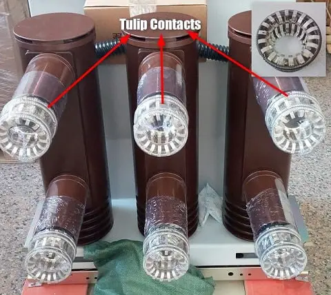
    Tulip contacts of Vacuum Circuit Breaker
    Tulip contacts of Vacuum Circuit Breaker

    The advantage of this type of contact is that arcing is confined to the regions which are not in contact in the fully engaged position.

    2) Finger and wedge contacts
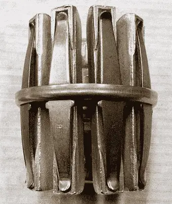
    This type of contact is largely used for low-voltage oil circuit breakers owing to the general unsuitability for use with arc control devices.
    Finger Contact in Circuit Breaker
    Finger Contact in Circuit Breaker

    3) Butt contacts

    The butt type contact and is formed by the springs. It possesses two advantages. 

    • Firstly, the spring pressure is available to assist contact separation. This is useful in single-break oil circuit breakers and air-blast circuit breakers where relatively small “loop” forces are available to assist in opening. 
    • Secondly, there is no gripping force so that this type of contact is especially suitable for higher short circuit rating.

    In modern vacuum interrupters, three contact designs dominate. The first is the butt contact, the second is the transverse magnetic field (TMF) contact, and the third is the axial magnetic field (AMF) contact.

    Instrument Transformers

    In a modern power system, the circuits operate at very high voltages and carry current of thousands of amperes. The measuring instruments and protective devices cannot work satisfactorily if mounted directly on the power lines. This difficulty is overcome by installing instrument transformers on the power lines. 

    The function of these instrument transformers is to transform voltages or currents in the power lines to values which are convenient for the operation of measuring instruments and relays.

    There are two types of instrument transformers viz.

    1. Current transformer (C.T.)
    2. Potential transformer (P.T.)
    The primary of the current transformer is connected in the power line. The secondary winding provides for the instruments and relays a current which is a constant fraction of the current in the line.

    Similarly, a potential transformer is connected with its primary in the power line. The secondary provides for the instruments and relays a voltage which is a known fraction of the line voltage. 

     Advantages of Instrument Transformers

    The use of instrument transformers permits the following advantages :
    • They isolate the measuring instruments and relays from high-voltage power circuits.
    • The leads in the secondary circuits carry relatively small voltages and currents. This permits to use wires of smaller size with minimum insulation.

    Bus-Bars and Conductors

    The current-carrying members in a circuit breaker consist of fixed and moving contacts and the conductors connecting these to the points external to the breaker. 
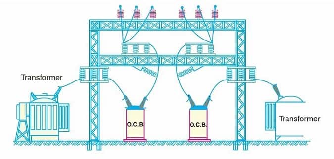
    Outdoor Switchgear
    Outdoor Switchgear

    If the switchgear is of the outdoor type, these connections are connected directly to the overhead lines. In case of indoor switchgear, the incoming conductors to the circuit breaker are connected to the busbars.
     

    Related Articles

    • Construction of High Voltage Current Transformer
      Basic Types of Current Transformers

      Current Transformers (CT’s) are instrument transformers that are used to supply a reduced value of…

    • types of electrical relays
      Types of Electrical Relays

      We have already discussed the working of electrical relays. Now we are going through different…

    • Stepper motor types
      Types of Stepper Motor

      A stepper motor is an electromechanical device which converts electrical pulses into discrete mechanical movements. …

    • all day efficiency of transformer
      All Day Efficiency of Transformer

      Definition The ratio of output in kWh to the input in kWh of a transformer…

    • 4 2Bmajor 2Btypes 2Bof 2Bsubstations
      4 Major Types of Electrical Substations

        The assembly of the apparatus used to change some characteristic (e.g. voltage, a.c. to…

    • Low voltage Switchgear
      Low Voltage Switchgear

      As per IEC 60947, switchgears with rated voltages up to 1000 V ac and 1500…

    • Share:
    author avatar
    Electrical Engineer

    Previous post

    Electronic Structure of Atom
    September 8, 2015

    Next post

    Air Break Switch - Types and Uses
    September 8, 2015

    You may also like

    Transformer testing at factory
    Percentage Reactance in Power System (Transformer, Generator or Reactor)
    16 January, 2023
    transformer-winding
    Transformer Windings: Types and Design
    22 November, 2022
    Photo by Sven Daniel on Unsplash
    What is CNC Machining? | Definition, Processes, Components & More
    3 November, 2022

    Leave A Reply Cancel reply

    Your email address will not be published. Required fields are marked *

    Search Here

    From Blog

    surge
    Voltage Surge in Power System
    05Sep2018
    Working of a DC motor
    Back EMF and Its Significance in DC Motor
    06Feb2015
    Working of a DC motor
    Objective Questions on Alternator | Part 1
    12Aug2014
    Programmable Logic Controllers
    The Basics of Programmable Logic Controller (PLC) that You Never Learned
    28Mar2020

    Categories

    • Alternator
    • Arduino
    • Basic Electrical
    • Battery
    • Books
    • Cables
    • Capacitor
    • Career
    • Circuit Breaker
    • Control System
    • DC Generator
    • DC Generator MCQ
    • DC Generator Solved Problems
    • DC Motor
    • DC Motor MCQ
    • Drives
    • Electric Vehicles
    • Electrical Circuits
    • Electrical Machines
    • Electrical Relays
    • Electrical Safety
    • Electronics
    • Embedded System
    • Exams
    • Generation
    • Guest Post
    • HVDC
    • Instrumentation
    • Interview Questions
    • Locomotives
    • MCQ
    • Measurement
    • Microcontroller
    • Objective Questions
    • PCB
    • PLC
    • Power System
    • Problems and Solution
    • Projects
    • Resistor
    • Signals and Systems
    • Single Phase Motors
    • Substation
    • Switchgear
    • Synchronous Motor
    • Three Phase Induction Motor
    • Transformer
    • Transmission Line
    • Uncategorized

    Copyright © 2021 Study Electrical, Inc.

    © StudyElectrical.Com 2021

    Login with your site account

    Lost your password?