The power transformer and distribution transformer are an important part of an electrical power distribution network. They are classified based on some of their characteristics.
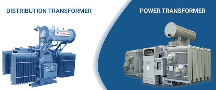
A power transformer is used in transmission network of higher voltages for step-up and step down the application (400 kV, 200 kV, 110 kV, 66 kV, 33 kV) and are generally rated above 200 MVA.
Distribution transformer is used for lower voltage distribution networks as a means to end user connectivity. (11 kV, 6.6 kV, 3.3 kV, 440 V, 230 V) and are generally rated less than 200 MVA.
Transformer Size / Insulation Level:
The power transformer is used for the transmission purpose at heavy load at a higher voltage greater than 33 kV and 100% efficiency.
It is big in size as compared to the distribution transformer. They are used in generating station and transmission substation with high insulation level.
Read more about electrical substations.
The distribution transformer is used for the distribution of electrical energy at low voltage as less than 33 kV in industrial purpose and 440 V-220 V in domestic purpose.
It works at low efficiency at 50-70%, small size, easy in installation, having low magnetic losses & it is not always fully loaded.
Iron Losses and Copper Losses
Power Transformers are used in Transmission network so they do not directly connect to the consumers, so load fluctuations are very less.
- Power Transformers are loaded fully during 24 hr’s a day, so Cu losses & Fe losses take place throughout the day. The specific weight i.e. (iron weight)/(copper weight) is very less.
- The average loads are nearer to full loaded or full load and these are designed in such a way that maximum efficiency at full load condition. These are independent of time so in calculating the efficiency only power basis is enough.
Read Percentage Impedance of Transformers.
Distribution Transformers are used in distribution network so directly connected to the consumer so load fluctuations are very high.
- These are not loaded fully at all time so iron losses take place 24 hours a day and copper losses take place based on load cycle.
- The specific weight is more i.e. (iron weight)/(copper weight) average loads are about only 75% of full load and these are designed in such a way that max efficiency occurs at 75% of full load.
- As these are time dependent the all-day efficiency is defined in order to calculate the efficiency.
Power transformers are used for transmission as a step up devices so that the I²R loss can be minimized for given power flow.
- These transformers are designed to utilize the core to the maximum and will operate very much near to the knee point of the B-H curve (slightly above the knee point value).
- This brings down the mass of the core enormously. Naturally, these transformers have the matched iron losses and copper losses at peak load (i.e. the maximum efficiency point where both the losses match).
Distribution transformers obviously cannot be designed like this. Hence the all-day-efficiency comes into picture while designing it.
- It depends on the typical load cycle for which it has to supply. Definitely, Core design will be done to take care of peak load and as well as all-day-efficiency. It is a bargain between these two points.
Power transformer generally operated at full load.
- Hence, it is designed such that copper losses are minimal.
However, a distribution transformer is always online and operated at loads less than the full load for most of the time.
- Hence, it is designed such that core losses are minimal.
In the power transformer, the flux density is higher than the distribution transformer.
Maximum Efficiency
The main difference between power and distribution transformer is the distribution transformer is designed for maximum efficiency at 60% to 70% load as normally doesn’t operate at full load all the time.
Its load depends on distribution demand.
Whereas power transformer is designed for maximum efficiency at 100% load as it always runs at 100% load being near to generating station.
Distribution Transformer is used at the distribution level where voltages tend to be lower. The secondary voltage is almost always the voltage delivered to the end consumer.
- Because of voltage drop limitations, it is usually not possible to deliver that secondary voltage over great distances.
- As a result, most distribution systems tend to involve many ‘clusters’ of loads fed from distribution transformers, and this, in turn, means that the thermal rating of distribution transformers doesn’t have to be very high to support the loads that they have to serve.
All-day efficiency = (Output in KWhr) / (Input in KWhr)
in 24 hrs which is always less than power efficiency.
| Power Transformer | Distribution Transformer |
|
|