What is Aeolian Vibration?
Aeolian vibration is a type of motion caused by wind on conductors and overhead shield wires of transmission and distribution lines. Aeolian vibration is characterised by low amplitude (conductor diameter) high frequency (5 to 150 Hz).
Aeolian vibration of conductors and overhead shield wires (OHSW) on transmission and distribution lines can produce damage that will negatively impact the reliability or serviceability of these lines.
In this phenomenon, conductor strand fatigue failures occur at the suspension clamps or at the clamps of the other devices installed on the conductor such as spacers, spacer dampers, dampers and other devices.
Lines damaged by vibration may have to be derated or even taken out of service until repairs can be made. This could have an impact on an entire network.
Read: Bundled Conductors in Transmission Lines
Wind causes a variety of motions on transmission line conductors. Important among them are
- Aeolian Vibration
- Subconductor oscillation
- Galloping
- Wind sway
Subconductor oscillation, galloping and wind sway are associated with higher wind velocity. These motions are generally characterized as low frequency and high amplitude. If these motions are not controlled, they can produce damage to the conductor and other elements in the transmission system.
Aeolian vibration, on the other hand, is associated with smooth non-turbulent winds in the range of 2 MPH (miles per hour) to 15 MPH and can occur on a daily basis. Aeolian vibration is characterized by high frequency and low amplitude motion.
This article describes the theory and mechanism of aeolian vibration, effects of aeolian vibration and different dampers used to reduce the harmfull effect of aeolian vibration.
How Aeolian Vibration Occurs?
Aeolian vibrations occur when a smooth wind flow of 2 to 15 mph (1 to 7 m/s) interacts a conductor.
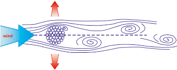
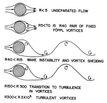
When this happens, air accelerates to go around the conductor and then separates behind it as seen in Figure below.
This motion creates a low-pressure region at the opposite side of the conductor and the air shows a tendency to move
into this vacuum zone. This is the vortex shedding action that creates an alternating pressure imbalance causing the conductor to move up and down at a ninety-degree angle to the flow direction.
On the other hand, winds higher than 15 mph usually contain a considerable amount of turbulence and decrease the generation of the vortices.
Theory/Mechanism of Aeolian Vibration
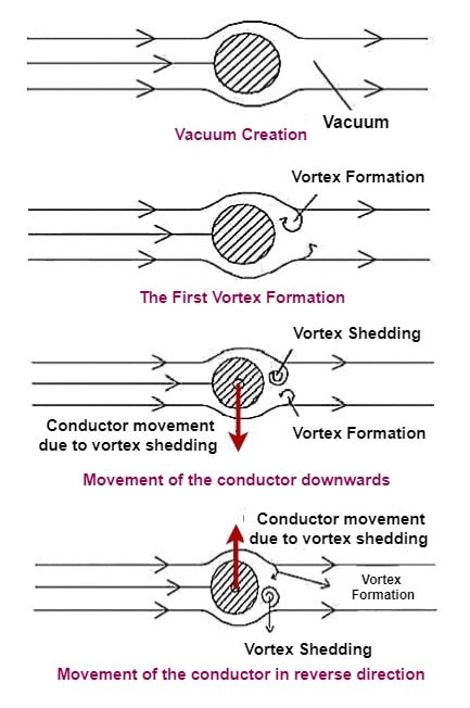
When a “smooth” stream of air passes across a cylindrical shape, such as a conductor or overhead shield wires, vortices (eddies) are formed on the leeward side (back side).
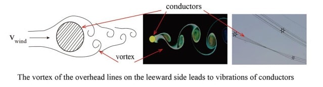
These vortices alternate from the top and bottom surfaces and create alternating pressures that tend to produce movement at right angles to the direction of the air flow. This is the mechanism that causes aeolian vibration.
The term “smooth” was used in the above description because unsmooth air (i.e., air with turbulence) will not generate the vortices and associated pressures. The degree of turbulence in the wind is affected both by the terrain over which it passes and the wind velocity itself.
It is for these reasons that aeolian vibration is generally produced by wind velocities below 15 miles per hour (MPH). Winds higher than 15 MPH usually contain a considerable amount of turbulence, except for special cases such as open bodies of water or canyons where the effect of the terrain is minimal.
The frequency at which the vortices alternate from the top to bottom surfaces of conductors and shield wires can be closely approximated by the following relationship that is based on the Strouhal Number.
Vortex Frequency (Hertz) = 3.26V / d
where: V is the wind velocity component normal to the conductor or OHSW in miles per hour
d is the conductor or OHSW diameter in inches
3.26 is an empirical aerodynamic constant
One thing that is clear from the above equation is that the frequency at which the vortices alternate is inversely proportional to the diameter of the conductor or OHSW.
For example, the vortex frequency for a 795 kcmil 26/7 ACSR (“Drake”) conductor under the influence of an 8 MPH wind is 23.5 Hertz.
A 3/8” OHSW under the same 8 MPH wind will have vortices alternating at 72.4 Hertz. The fact that the vortex frequency for an OHSW is much higher than that for a conductor will be important to remember when the effects of vibration are discussed.
Sustained aeolian vibration activity occurs when the vortex frequency closely corresponds to one of the natural vibration frequencies of the span of conductor or OHSW. This sustained vibration activity takes the form of discrete standing waves with forced nodes at the support structures and intermediate nodes spaced along the span at intervals that depend on the particular natural frequency.
Factors Affecting Aeolian Vibration
The main factors affecting the aeolian vibrations are
- the span length,
- the tension and
- the mechanical impedance of the conductor.
The amount of mechanical energy passing through the conductor increases with the span length.
An increase in tension, on the other hand, raises the vibration tendency of a conductor due to a decline in its natural self-damping.
Finally, the mechanical impedance is determined by the mechanical and material properties of the conductor.
Therefore, maximum vibration amplitude is generally equal to the conductor diameter when the most serious aeolian vibrations occur by steady winds at the long spans with high conductor tensions in the smooth terrain.
Aeolian vibration creates dynamic bending stresses on the conductor which cause the fatigue failure of strands at the supporting locations when the endurance limit of the strands is exceeded.
Failure time depends on the magnitude of the bending stresses and the number of bending cycles that exceed the endurance limit of the strands.
During warmer months, bending stresses are generally below the endurance limit but they usually exceed the endurance limit during the winter since the tensions are higher that reduce the motility of the conductor (self-damping).
Effects of Aeolian Vibration
It should be understood that the existence of aeolian vibration on a transmission or distribution line doesn’t necessarily constitute a problem. However, if the magnitude of the vibration is high enough, damage in the form of abrasion or fatigue failures will generally occur over a period of time.
The two important effects of Aeolian vibration are
- Abrasion Damage
- Fatigue Failure
Abrasion is the wearing away of the surface of a conductor or OHSW and is generally associated with loose connections between the conductor or OHSW and attachment hardware or other conductor fittings. The looseness that allows the abrasion to occur is often the result of excessive aeolian vibration.
Abrasion damage can occur within the span itself at spacers, spacer dampers and marker spheres, or at supporting structures.
Fatigue failures are the direct result of bending a material back and forth a sufficient amount over a sufficient number of cycles. Removing the pull tab from a can of soda is a good example.
All materials have a certain “endurance limit” related to fatigue. The endurance limit is the value of bending stress above which a fatigue failure will occur after a certain number of bending cycles, and below which fatigue failures will not occur, regardless of the number of bending cycles.
When the bending stresses in a conductor or OHSW due to aeolian vibration exceed the endurance limit, fatigue failures will occur. The time to failure will depend on the magnitude of the bending stresses and the number of bending cycles accumulated
Aeolian Vibration Damping Devices
In order to deal with the negative effects of aeolian vibration, a variety of impact and tuned dampers are designed.
Among them the most commonly used ones are
- Torsional dampers,
- Elgra dampers,
- Spiral dampers,
- Spring-piston dampers,
- Pneumatic dampers and
- Stockbridge dampers.
Torsional dampers, Elgra dampers, and spiral dampers are classified as the impact dampers that use collision energy to dissipate the vibration energy.
Torsional dampers simply increase the interstrand friction of the conductor as a result of the torsional motion produced by the offset weights when the conductor vibrates. They are effective on conductors smaller than about 12.5 mm in diameter (1/2″).
Unfortunately, torsional dampers are efficient in a narrow frequency range and have a tendency to freeze up in the winter. Elgra dampers, on the other hand, are effective to give different frequency responses with their variety of plate-type weights.
Spiral dampers are geometrically separated from the torsional dampers and the Elgra dampers but they also suppress the vibration by impacting against the conductor.
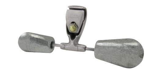
Spring-piston dampers, pneumatic dampers, and Stockbridge dampers are classified as the tuned dampers which are effective when their natural frequency coincide with the excitation frequency of the conductor.
Unlike the spring-piston dampers and the pneumatic dampers, the Stockbridge dampers can be tuned to be effective over a wide range of frequency and they can dissipate vibrations in any directions.