• Home
  • Courses
  • Machines
    • Transformer
    • AC Motors
      • Induction Motor
      • Synchronous Motor
    • DC Motor
    • DC Generator
  • Power System
    • Circuit Breaker
    • Switchgear
    • Substation
    • Control System
    • Measurement
  • Electronics
  • Blog
  • Contact
    • Contact Us
    • Privacy Policy
Have any question?
[email protected]
RegisterLogin
StudyElectrical.Com
  • Home
  • Courses
  • Machines
    • Transformer
    • AC Motors
      • Induction Motor
      • Synchronous Motor
    • DC Motor
    • DC Generator
  • Power System
    • Circuit Breaker
    • Switchgear
    • Substation
    • Control System
    • Measurement
  • Electronics
  • Blog
  • Contact
    • Contact Us
    • Privacy Policy

    Power System

    Low Voltage Circuit Breakers – Design and Construction Basics

    • Categories Power System, Circuit Breaker, Switchgear
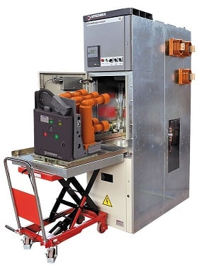
    Metal Clad Switchgear

    CIRCUIT%2BBREAKER%2BDESIGN%2BBASICS

    In this article, we are going to study the basics of low voltage circuit breaker design and construction. The operation and arc extinction of different types of circuit breakers were already discussed. The basic design principles of low rating circuit breakers (MCB, MCCB, GFCI, etc.) are explained here. Variations to these design principles will be discussed later.

    Circuit breakers are electrical switchgear which are constructed from the following five major components. 
    1. Frame
    2. Contacts
    3. Arc Chute Assembly
    4. Operating Mechanism
    5. Trip Unit

    The functions and features of each component are explained with pictures.

    Table of Contents

    • 1. Frame
    • 2. Contacts
      • Straight-Through Contacts
      • Blow-Apart Contacts
    • 3. Arc Chute Assembly
      • Operating Handle
    • 4. Operating Mechanism
    • 5. Trip Unit
      • Related Articles

    1. Frame

    The frame provides an insulated housing to mount the circuit breaker components. The construction material is usually a thermal set plastic, such as glass-polymer. The construction material can be a factor in determining the interruption rating of the circuit breaker. 

    Typical frame ratings include maximum voltage, maximum ampere rating, and interrupting rating.

    2. Contacts

    The current flowing in a circuit controlled by a circuit breaker flows through the circuit breaker’s contacts. When a circuit breaker is turned off or is tripped by a fault current, the circuit breaker interrupts the flow of current by separating its contacts.

    Contacts are of two types depending on the interrupting rating.
    • Straight-Through Contacts
    • Blow-Apart Contacts

    Straight-Through Contacts

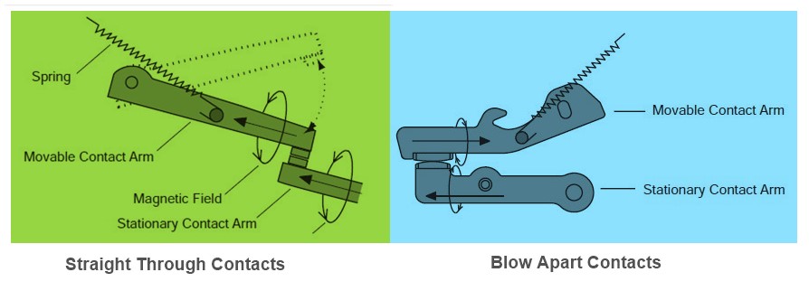
    Some circuit breakers use a straight-through contact arrangement, so-called because the current flowing in one contact arm continues in a straight line through the other contact arm.
    Straight-Through Contacts Blow-Apart Contacts
    Straight-Through Contacts and Blow-Apart Contacts

    Blow-Apart Contacts

    Blow-apart contact design is commonly used by circuit breakers with higher interrupting ratings. With this design, the two contact arms are positioned parallel to each other. 

    As current flows through the contact arms, magnetic fields develop around each arm. Because the current flow in one arm is opposite in direction to the current flow in the other arm, the two magnetic fields oppose each other. 
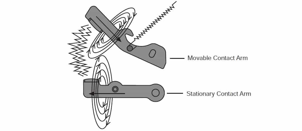
    Under normal conditions, the magnetic fields are not strong enough to force the contacts apart.

    2016 01 24 16h37 45

    When a fault develops, current increases rapidly causing the strength of the magnetic fields surrounding the contacts to increase as well. The increased strength of the opposing magnetic fields helps to open the contacts faster by forcing them apart.
     
    By reducing the time required to open circuit breaker contacts when a fault occurs, the blow-apart contact design reduces the damaging heat felt by the circuit protected by the circuit breaker.

    3. Arc Chute Assembly

    The arc is extinguished in this assembly. The current flowing in a circuit controlled by a circuit breaker flows through the circuit breaker’s contacts.

    When a circuit breaker is turned off or is tripped by a fault current, the circuit breaker interrupts the flow of current by separating its contacts.

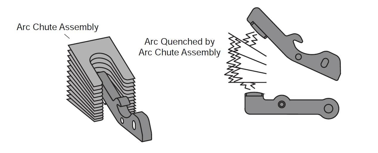
    This assembly is made up of several “U” shaped steel plates that surround the contacts. As the arc developes, it is drawn into the arc chute where it is divided into smaller arcs, which are extinguished faster.
    Arc Chute Assembly
    Arc Chute Assembly
    Minimizing the arc is important for two reasons. 
    • First, arcing can damage the contacts. 
    • Second, the arc ionizes gases inside the molded case. 
    If the arc isn’t extinguished quickly the pressure from the ionized gases can cause the molded case to rupture. 

    Arcing phenomenon and methods of arc extinction were discussed in previous articles. 

    Operating Handle

    A circuit breaker must provide a manual means for energizing and de-energizing a circuit and must be capable of being reset after a fault condition has been cleared.

    These capabilities are typically provided through the use of an operating handle.

    Operating Handle
    Operating Handle
     
    Molded case circuit breakers (MCCBs) are trip free, meaning that they cannot be prevented from tripping by holding or blocking the operating handle in the “ON” position.
     
    There are three positions of the operating handle: “ON” (contacts closed), “OFF” (contacts open), and “TRIPPED” (mechanism in tripped position, contacts open). The circuit breaker is reset after a trip by moving the handle to the “OFF” position and then to the “ON” position.

    4. Operating Mechanism

    The operating handle is connected to the moveable contact arm through an operating mechanism.

    In the following illustration, the operating handle is moved from the “OFF” to the “ON” position (Figure 1). In this process, a spring begins to apply tension to the mechanism.

    When the handle is directly over the center, the tension in the spring is strong enough to snap the contacts closed. This means that the speed of the contact closing is independent of how fast the handle is operated.
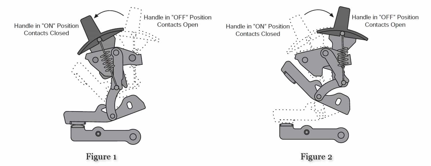
    Operating Mechanism
    Operating Mechanism of Low Rating Circuit Breakers

    The contacts are opened by moving the operating handle from the “ON” to the “OFF” position (Figure 2). In this process, spring begins to apply tension to the mechanism.

    When the handle is directly over the center, the tension in the spring is strong enough to snap the contacts open. Therefore, contact opening speed is also independent of how fast the handle is operated.

    5. Trip Unit

    In addition to providing a means to open and close its contacts manually, a circuit breaker must automatically open its contacts when an overcurrent is sensed. The trip unit is the part of the circuit breaker that determines when the contacts will open automatically.
    Thermal Magnetic Trip Unit
    Thermal Magnetic Trip Unit
     
    In a thermal-magnetic circuit breaker, the trip unit includes elements designed to sense the heat resulting from an overload condition and the high current resulting from a short circuit. In addition, some thermal-magnetic circuit breakers incorporate a “Push-to-Trip” button.

    Related Articles

    • minimum oil circuit breaker
      Oil Circuit Breakers - Types, Working and Construction

      In oil circuit breakers, some insulating oil (e.g., transformer oil) is used as an arc…

    • Low voltage Switchgear
      Low Voltage Switchgear

      As per IEC 60947, switchgears with rated voltages up to 1000 V ac and 1500…

    • ACB Air Circuit Breaker
      Working of Air Circuit Breakers

      What is an ACB? A circuit breaker in which the contacts open and close in…

    • interview question circuit breaker
      Circuit Breakers - Interview Questions with Answers

      1. What is a Circuit Breaker? Circuit Breaker is a mechanical device designed to close…

    • Square D Circuit Breaker
      Square D QO Circuit Breakers

      QO stands for Qwik-Open. Square D QO Circuit Breakers are fastest tripping circuit breakers at…

    • Sulphur Hexafluoride SF6 Circuit Breakers Construction Working and Advantages
      SF6 Circuit Breakers - Construction, Types and Working

      In an SF6 Circuit breaker, sulphur hexafluoride gas is used as the arc quenching medium. The…

    • Share:
    author avatar
    Electrical Engineer

    Previous post

    Sag in Overhead Transmission Lines
    January 24, 2016

    Next post

    Video - How Single Phase Induction Motor Works?
    February 10, 2016

    You may also like

    Transformer testing at factory
    Percentage Reactance in Power System (Transformer, Generator or Reactor)
    16 January, 2023
    Load Curve and Load Duration Curve
    Load Duration Curve in Power Station
    29 September, 2022
    Double end break disconnect switch
    Disconnect Switches (Isolator) in Substation: Types, Design and Working
    1 September, 2022

      1 Comment

    Leave A Reply Cancel reply

    Your email address will not be published. Required fields are marked *

    Search Here

    From Blog

    Slip ring Construction
    Slip Rings and Their Connection to Modern Engineering
    28Jul2022
    cheerful coworkers in office during company 2LW3KS7
    Buy Cheap Essay: What Do Custom Sites Do for Students?
    26Sep2022
    Open Delta Connection in Transformer
    Open Delta (V-V) Connection of Transformers
    21Nov2019
    KU273L0WTW
    Introduction to Signals with Examples
    13Sep2022

    Categories

    • Alternator
    • Arduino
    • Basic Electrical
    • Battery
    • Books
    • Cables
    • Capacitor
    • Career
    • Circuit Breaker
    • Control System
    • DC Generator
    • DC Generator MCQ
    • DC Generator Solved Problems
    • DC Motor
    • DC Motor MCQ
    • Drives
    • Electric Vehicles
    • Electrical Circuits
    • Electrical Machines
    • Electrical Relays
    • Electrical Safety
    • Electronics
    • Embedded System
    • Exams
    • Generation
    • Guest Post
    • HVDC
    • Instrumentation
    • Interview Questions
    • Locomotives
    • MCQ
    • Measurement
    • Microcontroller
    • Objective Questions
    • PCB
    • PLC
    • Power System
    • Problems and Solution
    • Projects
    • Resistor
    • Signals and Systems
    • Single Phase Motors
    • Substation
    • Switchgear
    • Synchronous Motor
    • Three Phase Induction Motor
    • Transformer
    • Transmission Line
    • Uncategorized

    Copyright © 2021 Study Electrical, Inc.

    © StudyElectrical.Com 2021

    Login with your site account

    Lost your password?

    Not a member yet? Register now

    Register a new account

    Are you a member? Login now