• Home
  • Courses
  • Machines
    • Transformer
    • AC Motors
      • Induction Motor
      • Synchronous Motor
    • DC Motor
    • DC Generator
  • Power System
    • Circuit Breaker
    • Switchgear
    • Substation
    • Control System
    • Measurement
  • Electronics
  • Blog
  • Contact
    • Contact Us
    • Privacy Policy
Have any question?
[email protected]
Login
StudyElectrical.Com
  • Home
  • Courses
  • Machines
    • Transformer
    • AC Motors
      • Induction Motor
      • Synchronous Motor
    • DC Motor
    • DC Generator
  • Power System
    • Circuit Breaker
    • Switchgear
    • Substation
    • Control System
    • Measurement
  • Electronics
  • Blog
  • Contact
    • Contact Us
    • Privacy Policy

    Switchgear

    Low Voltage Switchgear

    • Categories Switchgear, Circuit Breaker, Electrical Relays, Generation, Instrumentation, Measurement, Power System, Substation
    Low voltage Switchgear

    As per IEC 60947, switchgears with rated voltages up to 1000 V ac and 1500 V dc are termed as low voltage switchgear.

    The term ‘switchgear’ is a generic term encompassing a wide range of products like circuit breakers, switches,  switch fuse units, off-load isolators, HRC fuses, contactors, earth leakage circuit breakers (ELCBS), miniature circuit breakers (MCBS), and moulded case circuit breakers (MCCBS), among others.

    A commonly followed network combination in LV distribution boards in shown in the figure below. It is a combination of power control centres and motor control centres or load distribution boards including lighting distribution boards.

    The incomer/sub-incomer/ distribution network generally depends on the capacity of the source and the distribution of load centres.

    2017 11 06 12h04 11 vert
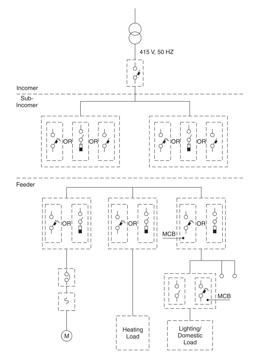
    Conventional Low Voltage Distribution Network

    The characteristics and feature of load controlling and protecting devices vary on the basis of the locations. The system being most commonly followed currently is detailed below.

    Table of Contents

    • Conventional Incomer
    • Conventional Sub-Incomer
    • Conventional Feeder Protection
    • Related Articles

    Conventional Incomer

    The devices used in the incomer should be capable of:

    1. Switching and carrying normal currents (generally above 1200 A);
    2. Withstanding abnormal currents for a short duration in order to allow downstream devices  to operate;
    3. Interrupting the maximum value of the fault current generated in the system;
    4. Ensuring the safety to the operating personnel;
    5. Inter-locking with downstream equipment; and
    6. Facilitating easy maintenance.

    ln the past, oil circuit breakers (OCBS), re-wireable fused isolators and air circuit breakers (ACBs) were the commonly used devices.

    However, ACB has been acknowledged as an idea device for incomer in terms of the safety, reliability and maintenance needs of the system.

    This is mainly due to its various characteristics like quick-make, quick-break stored energy type reliable mechanism, safety interlocks/ indications, ease of maintenance and its ability to withstand fault currents for a specified duration (1-3 secs) thereby allowing the feeder device to isolate the faulty branch of the network and ensuring reliable supply to healthy areas.

    Conventional Sub-Incomer

    The devices installed as parts of a sub-incomer should have the following characteristics

    • Ability to achieve economy without sacrificing protection and safety
    • Capability to withstand abnormal currents; and
    • Need for relatively less number of inter-locking indicating accessories since it covers a limited area of network.

    ACB’s and switch fuse units (SFUS) are, to a large extent, being used as sub-incomers along with modern devices like moulded case circuit breakers (MCCBs).

    Conventional Feeder Protection

    Feeder protection covers all load centres like motor control centres, lighting switchboards and industrial load centres.

    The choice of feeder protection device based on the different conventional feeder load centres are discussed below.

     1. Motor Control

    The motor feeder needs to be protected against the following eventualities in addition to normal switching control:

    • Short-circuit;
    • Over-currents up to locked rotor condition; and
    • Single-phasing.

    Requirements for Motor Control

    CharacteristicsDevices
    Switching normal currentsContactors
    Single-phasing sensingBi-metallic Relay
    Over—current (up to locked rotor condition) sensingBi-metallic Relay
    Switching over-currents including single-phasing current as aboveContactors
    Short-circuit currentMCCB/SFU
    LogicTimers/Auxiliary ; Contactors and other Accessories

    2. Other Industrial Load Control

    Loads like oven, pre-treatment and electroplating baths fall under this category and the feeders need to be protected against faulty over-currents.

    Presently MCCBs (https://studyelectrical.com/2015/01/moulded-case-circuit-breakers-mccb.html) and SFUs are being commonly used for this purpose.

    3. Lighting/Domestic Load Control

    The requirements of domestic load control are similar to those listed in other industrial load control with the addition of earth leakage current protection in order to reduce any damages to life and property that could be caused by harmful leakages of electric current and fire.

    In a low voltage power distribution system, electrical appliances are protected against damages from over-loads or short-circuits by fuses or circuit breakers.

    However, the human operator is not adequately protected when a fault occurs within the appliance itself. Hence the need for fast acting ELCBs operating on low leakage currents arises.

    The device, which detects leakage current as low as 100 mA and is capable of disconnecting equipment in less than 100 msec is called an earth leakage circuit breaker (ELCB) (https://studyelectrical.com/2015/05/residual-current-circuit-breakers-elcb-rccb-rcbo-working-principle.html) .

    The following two types of ELCBs are used depending upon the parameters to be detected:

    1. Voltage-operated ELCB; and
    2. Current-operated ELCB.

    Related Articles

    • Metal Clad Switchgear
      Low Voltage Circuit Breakers - Design and Construction Basics

      In this article, we are going to study the basics of low voltage circuit breaker…

    • surge
      Voltage Surge in Power System

      What is Voltage Surge or Transient Voltage? The sudden rise in voltage for a very…

    • fUNCTION OF PROTECTIVE RELAYS
      Function of Protective Relays in Power System

      We usually think of an electric power system in terms of its more impressive parts…

    • Tulip contacts of Vacuum Circuit Breaker
      Basic Types of Switchgear Components

      Before learning about different switchgear components, let us understand what is switchgear. The apparatus used…

    • types of electrical relays
      Types of Electrical Relays

      We have already discussed the working of electrical relays. Now we are going through different…

    • dc motor voltage and power equations
      Voltage and Power Equations of DC Motor | Condition of Maximum Power

      In this post, we will look at the voltage and power equation of a dc motor and…

    • Share:
    author avatar
    Electrical Engineer

    Previous post

    Arduino DC Digital Voltmeter
    November 6, 2017

    Next post

    Core Type and Shell Type Transformers
    November 13, 2017

    You may also like

    solenoid valve
    Here is Why Your Equipment Needs Solenoid Valves
    21 January, 2023
    Transformer testing at factory
    Percentage Reactance in Power System (Transformer, Generator or Reactor)
    16 January, 2023
    impact-of-not-calibrating-your-equipment
    The 5 Rules for Instrument Calibration
    1 November, 2022

    Leave A Reply Cancel reply

    Your email address will not be published. Required fields are marked *

    Search Here

    From Blog

    solenoid valve
    Here is Why Your Equipment Needs Solenoid Valves
    21Jan2023
    Diesel Locomotive Working Schematic
    How Diesel Locomotives (Diesel Trains) Work?
    01May2014
    KU273L0WTW
    Introduction to Signals with Examples
    13Sep2022
    Open Delta Connection in Transformer
    Open Delta (V-V) Connection of Transformers
    21Nov2019

    Categories

    • Alternator
    • Arduino
    • Basic Electrical
    • Battery
    • Books
    • Cables
    • Capacitor
    • Career
    • Circuit Breaker
    • Control System
    • DC Generator
    • DC Generator MCQ
    • DC Generator Solved Problems
    • DC Motor
    • DC Motor MCQ
    • Drives
    • Electric Vehicles
    • Electrical Circuits
    • Electrical Machines
    • Electrical Relays
    • Electrical Safety
    • Electronics
    • Embedded System
    • Exams
    • Generation
    • Guest Post
    • HVDC
    • Instrumentation
    • Interview Questions
    • Locomotives
    • MCQ
    • Measurement
    • Microcontroller
    • Objective Questions
    • PCB
    • PLC
    • Power System
    • Problems and Solution
    • Projects
    • Resistor
    • Signals and Systems
    • Single Phase Motors
    • Substation
    • Switchgear
    • Synchronous Motor
    • Three Phase Induction Motor
    • Transformer
    • Transmission Line
    • Uncategorized

    Copyright © 2021 Study Electrical, Inc.

    © StudyElectrical.Com 2021

    Login with your site account

    Lost your password?