
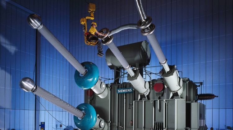
An electrical power transformer has to go through a number of transformer testing procedures for confirming its specifications and performances. In this article, you will learn different types of transformer testing methods, test setup, and their acceptance criteria.
Type of transformer testing methods
The transformer testing methods are broadly divided into two based on where the test is conducted.
- Tests conducted at the factory
- Tests conducted at the site
Some of the tests are done at the factory during the manufacturing process. Other tests are done at the site at the time of the transformer installation.
Tests Conducted at Factory:
- Type Tests
- Routine Tests
- Special Tests
The routine tests are performed on all transformers. But type tests are performed on each unique design.
Tests Conducted at Site:
- Pre-Commissioning Tests
- Periodic/Condition Monitoring Tests
- Emergency Tests
Each of the above tests contains a series of tests which are briefly explained below. We will discuss each of the tests in detail in coming articles.
Type tests of transformer
To prove that the transformer meets the customer’s specifications and design expectations, the transformer has to go through different testing procedures in manufacturer premises.
Some transformer testing methods are carried out for confirming the basic design expectation of that transformer.
Type tests are done mainly in a prototype unit not in all manufactured units in a lot. The type tests of the transformer confirm the main and basic design criteria of a production lot.
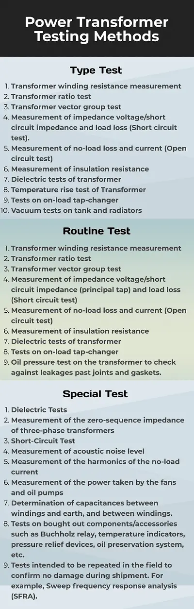
Type tests of transformer include:
- Transformer winding resistance measurement
- Transformer ratio test
- Transformer vector group test
- Measurement of impedance voltage/short circuit impedance and load loss (Short circuit test).
- Measurement of no-load loss and current (Open circuit test)
- Measurement of insulation resistance
- Dielectric tests of transformer
- Temperature rise test of Transformer
- Tests on on-load tap-changer
- Vacuum tests on tank and radiators
Routine tests of transformer
Routine tests of the transformer are mainly for confirming the operational performance of an individual unit in a production lot. Routine tests are carried out on every unit manufactured.
All transformers are subjected to the following routine tests:
- Transformer winding resistance measurement
- Transformer ratio test
- Transformer vector group test
- Measurement of impedance voltage/short circuit impedance (principal tap) and load loss (Short circuit test)
- Measurement of no-load loss and current (Open circuit test)
- Measurement of insulation resistance
- Dielectric tests of transformer
- Tests on on-load tap-changer
- Oil pressure test on the transformer to check against leakages past joints and gaskets.
Special tests of transformer
Special tests of the transformer are done as per customer requirement to obtain information useful to the user during the operation or maintenance of the transformer.
Special Tests of transformer include:
- Dielectric Tests
- Measurement of the zero-sequence impedance of three-phase transformers
- Short-Circuit Test
- Measurement of acoustic noise level
- Measurement of the harmonics of the no-load current
- Measurement of the power taken by the fans and oil pumps
- Determination of capacitances between windings and earth, and between windings.
- Tests on bought out components/accessories such as Buchholz relay, temperature indicators, pressure relief devices, oil preservation system, etc.
- Tests intended to be repeated in the field to confirm no damage during shipment. For example, Sweep frequency response analysis (SFRA).
Pre-Commissioning test of transformer
In addition to the above transformer testing methods, the power transformer also goes through some other tests, performed on it, before the actual commissioning of the transformer at the site.
The transformer testing performed before commissioning the transformer at the site is called the pre-commissioning test of the transformer.
Various pre‐commissioning checks and tests are performed to ensure the healthiness of the power transformer prior to its energization.
The important pre-commissioning tests are:
- Core insulation tests
- Operational checks on the protection system.
- Insulation resistance (IR) measurement.
- Capacitance and dissipation factor (tanδ) measurement of bushings.
- Capacitance and dissipation factor (tanδ) measurement of windings.
- Turns ratio (Voltage ratio) measurement.
- Vector Group and Polarity.
- Winding resistance measurement.
- Magnetic Balance test.
- Floating neutral point measurement.
- Measurement of short-circuit impedance.
- Exciting / Magnetizing current measurement
- Vibration measurement of the oil‐immersed reactor.
- Dissolved gas analysis (DGA) of oil samples.
These tests are done to assess the condition monitoring of the transformer after installation and compare the test results of all the low voltage tests with the factory test reports.
Condition Monitoring Tests
Condition monitoring for transformers is the process of monitoring the parameters of conditions in transformer (moisture, temperature, etc.), in order to identify a significant change which is indicative of a developing fault.
The condition monitoring tests of transformer include
- Winding resistance measurements
- Capacitance and tan δ
- Insulation Resistance (IR) and Polarization Index (PI) measurements
- Oil parameters
- Dissolved Gas Analysis (DGA)
- Furfuraldehyde Analysis
- Degree of Polymerization (DP)
- Partial Discharge (PD) Measurements
- Frequency Response Analysis (FRA)
- Recovery Voltage Measurements
- Capacitance and tan δ for bushings
Important Transformer Testing Methods
Now we will discuss some of the important transformer testing methods briefly.
1. Winding Resistance Measurement (Resistance)
This transformer testing method is conducted to determine the resistance. Winding Resistance Measurement is one of the routine tests in a transformer.
PURPOSE:
The aim of winding resistance measurement in a transformer is to measure the resistance of all windings in the transformer under test in order that the I²R losses can be calculated.
Also, to verify, through acceptable resistance readings, that all bolted connections are tight, and that crimped connections and conductor splices are adequate.
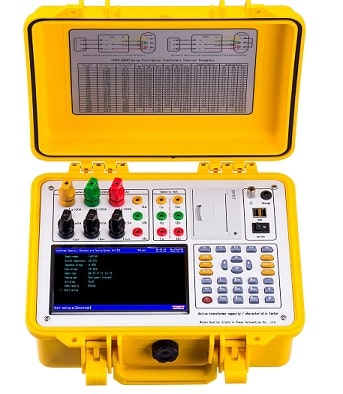
SETUP:
A digital Wheatstone or Kelvin bridge is used to apply a very low DC current to each of the HV and LV windings which return the result in ohms. These are used to measure low resistances (below 10 Ohms).
The low current is necessary to insure against heating of the windings which would lead to false readings due to an increase in resistance.
PASS CRITERIA:
The variation in resistance measurements between phases of the same winding shall not exceed the limits specified by the transformer manufacturer.
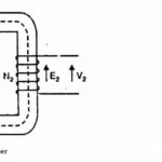
2. Ratio Measurement and Vector Relationship Check
This transformer testing method checks the Voltage Turns Ratio, Polarity, and Phase Relation of the transformer.
PURPOSE:
- To verify the voltage ratio of each coil in the transformer under test by checking the turns ratio of the HV and LV windings and
- And to verify that the windings are connected correctly to provide the specified primary to secondary
vector relationship.
SETUP:
A ratiometer is used to perform this test.
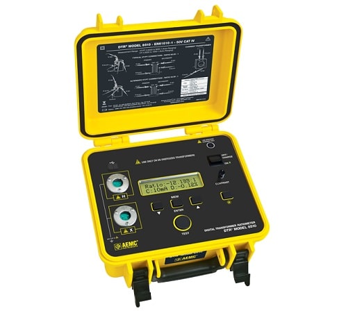
This equipment connects to each phase of the HV and LV winding and via the application of a very low voltage determines the ratio of the high voltage windings to the low voltage windings. These values are compared to those supplied from Engineering.
Here is a video of using Voltage Turns Ratiometer (VTRM) for measuring the turns ration and polarity.
PASS CRITERIA:
- Ratio: Compute ratio tolerances from nominal transformer rated voltages. Maximum tolerances from calculated ratio = ±0.5%.
- Vector Relationship: A correct ratio will verify the desired vector relationship or polarity. A test that yields no ratio at all or one that is far different than the calculated ratio may indicate a connection problem in the transformer under test.
- Note:- A large difference between exciting current readings while rationing different coils of a transformer may indicate a problem such as a turn-to-turn short.
Update:
Rule of Thumb: For Faulty Transformer (using a Ratiometer).
Turns Ratio Difference <0.5%. Measured Phase Angle must be less than <10°
- If the measured ratio is less than the calculated value then the primary may have some short-circuited turns.
- If the measured ratio is greater than the calculated value then the secondary may have some short-circuited turns.
3. No Load Loss and Excitation Current Measurement
Core Loss and Exciting Current
PURPOSE:
To measure no-load loss (core loss) and excitation current, and verify that these values are within an acceptable tolerance of the calculated values.
This will confirm that the core design (i.e. cross-sectional area and lamination thickness) is adequate to handle the required flux density and that the cores were properly assembled.
SETUP:
The secondary terminals of the transformer under test is connected to a variable AC voltage source with no connections to the primary bushings.
The voltage is gradually increased until the full rated voltage is obtained. The core loss in watts, as well as the current, is recorded and compared to design data supplied by Engineering.
PASS CRITERIA:
Core loss shall not exceed design value by more than 10%.
Maximum excitation current:
- For Wound Core – 2%
- For Stacked Core – 5%
If tested core loss exceeds the maximum allowance, another test shall be made at 110% of rated secondary voltage, and the resulting data shall be submitted to a design engineer for review.
4. Load Loss and Impedance
PURPOSE:
To determine, by test and calculation, load losses and total losses of a transformer under test.
Also, to determine the impedance voltage of the transformer expressed as a percentage of the rated primary voltage, from which may be calculated the winding currents under short circuit conditions.
The losses obtained from this test combined with the core loss data validates if the transformer tank and radiators are sufficient to allow for proper cooling.
SETUP:
The LV terminals are shorted together. The HV terminals are connected to a variable AC voltage source. Voltage is then applied to the HV and increased until such time that rated current is reached. The voltage and wattage are recorded and compared to data supplied by Engineering.
PASS CRITERIA:
Tested total losses shall not exceed design losses by more than 6%.
The limits of tested impedance are ±7.5% of specified impedance.
Losses or impedance values that exceed limits should be submitted to engineering for review.
5. Induced Voltage Test (Induced Potential)
PURPOSE:
To verify coil and lead insulation levels by inducing the transformer under test to twice its rated voltage at high frequency for 7200 cycles.
This test verifies turn to turn and layer to layer insulation, as well as lead to lead insulation within the high voltage and low voltage lead assemblies.
SETUP:
This test is performed using a high-frequency generator (180 HZ). Since the frequency and inductive reactance are inversely proportional, the double voltage required for this test is made possible because the core does not saturate.
PASS CRITERIA:
There should be no collapse or pull-down of the test voltage. Smoke and bubbles from coils or lead assemblies may also indicate an insulation failure.
6. Applied Potential Test (Hi-Pot Test)
This test is also called HiPot Test (High Potential Test)
PURPOSE:
To verify the adequacy of winding to winding, and winding to ground insulation in each coil of the transformer under test.
This transformer testing method also verifies the adequacy of all live-to-ground clearances in the transformer.
SETUP:
During this test, each winding is shorted out by connecting its bushings together. The ANSI specified voltage is then applied to the winding under test with the other windings connected to the ground.
No voltage is induced in the winding under test or magnetic flux induced in the core. Hence the insulation between turns or between layers in the winding under test is not stressed.
PASS CRITERIA:
Failure of a winding is indicated by loss of test voltage and/or test set circuit breaker tripping.
Failure can also be indicated by smoke and bubbles from coils or lead assemblies, or by an audible thump from inside the tank.
Tests 7 through 10 as listed above are not normally witnessed (for various reasons), but test data is available upon request at the time of the Factory Witness Test.
7. Production line impulse test
PURPOSE:
To verify, by application of two 1.2 x 50 µs negative impulse waves to each high voltage phase bushing, insulation levels and electrical clearances within the transformer under test.
This transformer testing method verifies the integrity of turn to turn, layer to layer, winding to winding, and lead to lead insulation, as well as live to live, and live to ground clearance distance.
Impulse tests simulate switching and lightning surges that may be impressed on the transformer.
SETUP:
The transformer under test is connected to the impulse generator. Each phase of each winding (HV and LV) is subjected to a voltage level dependent on the BIL (basic insulation level) of the winding under test.
The impulse generator is made up of a number of capacitors that are charged in parallel to a level that when
discharged in series will combine to achieve the required test voltage.
The image of the voltage surge through each winding is captured on an oscilloscope.
PASS CRITERIA:
There should be no significant differences between voltage traces, displayed on the oscilloscope, from any HV bushing.
Particular attention should be paid to the wave shape and voltage decay rate after the peak voltage of each voltage trace. Failure may also be indicated by an audible thump from the transformer tank, or by smoke
and bubbles from coils or lead assemblies.
8. Insulation resistance (“Megger”)
PURPOSE:
Insulation resistance tests are made to determine the insulation resistance from individual windings to the ground or between individual windings.
This transformer testing method will determine the condition of the insulation and that proper internal clearances have been met and maintained.
This test is performed as a routine test on 501kVA and larger transformers.
SETUP:
A digital megger with a maximum rating of 5 kV
PASS CRITERIA:
Insulation resistance measurements shall not be less than the minimum limits specified by the transformer manufacturer.
9. Insulation power factor
The ratio of power dissipated in the insulation in watts to the product of the effective voltage and current in volt-amperes when tested with a sinusoidal voltage.
This transformer testing method is used to give an indication of the condition (dryness) of the transformer insulation. There are no established limits for acceptable power factor readings in the transformer standards.
A power factor value of 1.0% or less for distribution transformers is generally used as an acceptable value.
SETUP:
The measurement is made with a capacitance bridge, measuring the capacitance between windings and between windings and ground, together with the power factor or loss angle of this capacitance.
10. Leak (pressure) test
PURPOSE:
To apply pressure and check for leaks on the transformer.
SETUP:
The completed transformer (cover welded) is pressurized at 7 PSI.
PASS CRITERIA:
UNIT HAS PASSED if no leaks are found and pressure remains constant (or does not drop more than expected with consideration of temperature differences) after a minimum of twelve (12) continuous hours under pressure.
UNIT HAS FAILED if a leak is found or if the pressure drops more than expected. If leaks are detected, repair the transformer as needed.
If the pressure drops more than expected, investigate tank seams, handholes, cover-mounted bushings, etc., to
determine where the leak is located and repair the transformer as needed.
Reference: Pacific Crest Transformers


Comments are closed.