• Home
  • Courses
  • Machines
    • Transformer
    • AC Motors
      • Induction Motor
      • Synchronous Motor
    • DC Motor
    • DC Generator
  • Power System
    • Circuit Breaker
    • Switchgear
    • Substation
    • Control System
    • Measurement
  • Electronics
  • Blog
  • Contact
    • Contact Us
    • Privacy Policy
Have any question?
[email protected]
RegisterLogin
StudyElectrical.Com
  • Home
  • Courses
  • Machines
    • Transformer
    • AC Motors
      • Induction Motor
      • Synchronous Motor
    • DC Motor
    • DC Generator
  • Power System
    • Circuit Breaker
    • Switchgear
    • Substation
    • Control System
    • Measurement
  • Electronics
  • Blog
  • Contact
    • Contact Us
    • Privacy Policy

Electrical Machines

Ideal Transformer and Practical Transformer

  • Categories Electrical Machines, Power System, Substation, Transformer
ideal 2Btransformer 2Bphasor 2Bdiagram

Table of Contents

  • Ideal Transformer
    • Phasor Diagram of Ideal Transformer
  • Practical Transformer
    • 1. Iron Losses
    • 2. Winding resistances
    • 3. Leakage reactances
    • Related Articles

Ideal Transformer

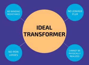
An ideal transformer is one that has
  1. no winding resistance
  2. no leakage flux i.e., the same flux links both the windings
  3. no iron losses (i.e., eddy current and hysteresis losses) in the core
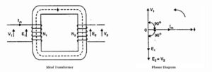
    Ideal 2Btransformer
    Ideal Transformer
Although an ideal transformer cannot be physically realized, yet its study provides a very powerful tool in the analysis of a practical transformer. In fact, practical transformers have properties that approach very close to an ideal transformer.
Ideal Transformer and Phasor Diagram

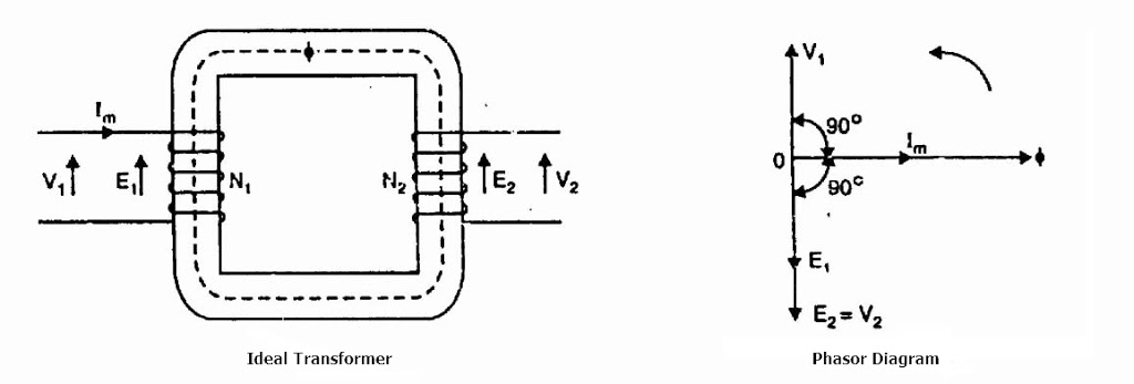
Consider an ideal transformer on no load i.e., the secondary is open-circuited as shown in the figure. Under such conditions, the primary is simply a coil of pure inductance.

When an alternating voltage V₁ is applied to the primary, it draws a small magnetizing current Iₘ which lags behind the applied voltage by 90°. This alternating current Iₘ produces an alternating flux ϕ which is proportional to and in phase with it.

The alternating flux ϕ links both the windings and induces e.m.f. E₁ in the primary and e.m.f. E₂ in the secondary. The primary e.m.f. E₁ is, at every instant, equal to and in opposition to V₁  (Lenz’s law). Both e.m.f.s E₁, and E₂ lag behind flux ϕ by 90°. However, their magnitudes depend upon the number of primary and secondary turns.

Phasor Diagram of Ideal Transformer

The phasor diagram of an ideal transformer on no load is also shown above. Since flux ϕ is common to both the windings, it has been taken as the reference phasor.

The primary e.m.f. E₁ and secondary e.m.f. E₂ lag behind the flux ϕ by 90°.

Note that E₁ and E₂ are in phase. But E₁ is equal to V₁ and 180° out of phase with it.

Practical Transformer

A practical transformer differs from the ideal transformer in many respects. The practical transformer has,
  1. iron losses,
  2. winding resistances and,
  3. magnetic leakage, giving rise to leakage reactance.

1. Iron Losses

Since the iron core is subjected to alternating flux, there occurs eddy current and hysteresis loss in it. These two losses together are known as iron losses or core losses.

The iron losses depend upon the supply frequency, the maximum flux density in the core, volume of the core, etc.

It may be noted that the magnitude of iron losses is quite small in a practical transformer.

2. Winding resistances

Since the windings consist of copper conductors, it immediately follows that both primary and secondary will have winding resistance. The primary resistance R₁ and secondary resistance R₂ act in series with the respective windings as shown in the figure.

When current flows through the windings, there will be power loss as well as a loss in voltage due to IR drop. This will affect the power factor and E₁ will be less than V₁ while V₂ will be less than E₂.

Practical 2BTransformer 2Bequivalent 2Bckt

3. Leakage reactances

Both primary and secondary currents produce flux. The flux ϕ which links both the windings is the useful flux and is called mutual flux.

However, the primary current would produce some flux ϕ which would not link the secondary winding. Similarly, the secondary current would produce some flux ϕ that would not link the primary winding.

The flux such as ϕ₁ or ϕ₂ which links only one winding is called leakage flux. The leakage flux paths are mainly through the air. The effect of these leakage fluxes would be the same as though inductive reactance were connected in series with each winding of the transformer that had no leakage flux as shown in the figure.

In other words, the effect of primary leakage flux ϕ₁ is to introduce an inductive reactance X₁ in series with the primary winding as shown. Similarly, the secondary leakage flux ϕ₂ introduces an inductive reactance X₂ in series with the secondary winding.

There will be no power loss due to leakage reactance. However, the presence of leakage reactance in the windings changes the power factor as well as there is voltage loss due to IX drop.

Leakage 2Bflux 2Bin 2Btransformer

Note.
Although leakage flux in a transformer is quite small (about 5% of ϕ)  compared to the mutual flux ϕ, yet it cannot be ignored.

It is because leakage flux paths are through the air of high reluctance and hence require considerable e.m.f. It may be noted that energy is conveyed from the primary winding to the secondary winding by mutual flux f which links both the windings.
Related Articles

  • properties 2Bof
    Properties of Good Transformer Oil

    Even though the basic functions of the oil used in transformers are heat conduction and electrical insulation, there…

  • Differences between Power Transformer and Distribution Transformer
    Working Principle of Transformer

    A transformer is a static piece of equipment used either for raising or lowering the…

  • Three Phase Transformer Connections
    Three Phase Transformer Interconnections

    The phase windings of three-phase transformers are interconnected to give a three-phase, three-or four-wire supply…

  • all day efficiency of transformer
    All Day Efficiency of Transformer

    The ratio of output in kWh to the input in kWh of a transformer over…

  • Differences between Power Transformer and Distribution Transformer
    Power Transformer and Distribution Transformer

    The power transformer and distribution transformer are an important part of an electrical power distribution…

  • Practical 2Btransformer 2Bon 2Bno 2Bload
    Practical Transformer on No Load

    Please read Ideal Transformer and Practical Transformer before continuing. Consider a practical transformer on no load…

  • Share:
author avatar
Electrical Engineer

Previous post

Properties of Good Transformer Oil
June 1, 2018

Next post

Why Current Transformer (CT) Seconday Should not be Open ?
June 10, 2018

You may also like

percentage_reactance transformer
Percentage Reactance in Power System (Transformer, Generator or Reactor)
16 January, 2023
transformer-winding
Transformer Windings: Types and Design
22 November, 2022
Photo by Sven Daniel on Unsplash
What is CNC Machining? | Definition, Processes, Components & More
3 November, 2022

    4 Comments

  1. Vasu
    March 31, 2019
    Reply

    Total chapter not given.

  2. Vasudeva Reddy
    March 31, 2019
    Reply

    Total chapter is not given

Leave A Reply Cancel reply

Your email address will not be published. Required fields are marked *

Search Here

From Blog

Underdamped, Overdamped and Critically damped Graphical Representation
Damping Systems – Air friction, Fluid Friction & Eddy Current Damping
26Nov2019
Auto Reclosing principle
Auto Reclosing of Power Lines and Types of Faults
15Feb2019
errors in mi
Errors in Moving Iron Instruments
19Sep2022
Electromagnetics Lecture Notes PDF
[PDF] Electromagnetism Lecture Notes – University of Cambridge
15Oct2019

Categories

  • Alternator
  • Arduino
  • Basic Electrical
  • Battery
  • Books
  • Cables
  • Capacitor
  • Career
  • Circuit Breaker
  • Control System
  • DC Generator
  • DC Motor
  • Drives
  • Electric Vehicles
  • Electrical Circuits
  • Electrical Machines
  • Electrical Relays
  • Electrical Safety
  • Electronics
  • Embedded System
  • Exams
  • Generation
  • Guest Post
  • HVDC
  • Instrumentation
  • Interview Questions
  • Locomotives
  • Measurement
  • Microcontroller
  • Objective Questions
  • PCB
  • PLC
  • Power System
  • Problems and Solution
  • Projects
  • Resistor
  • Signals and Systems
  • Single Phase Motors
  • Substation
  • Switchgear
  • Synchronous Motor
  • Three Phase Induction Motor
  • Transformer
  • Transmission Line
  • Uncategorized

Copyright © 2021 Study Electrical, Inc.

© StudyElectrical.Com 2021

Login with your site account

Lost your password?

Not a member yet? Register now

Register a new account

Are you a member? Login now