• Home
  • Courses
  • Machines
    • Transformer
    • AC Motors
      • Induction Motor
      • Synchronous Motor
    • DC Motor
    • DC Generator
  • Power System
    • Circuit Breaker
    • Switchgear
    • Substation
    • Control System
    • Measurement
  • Electronics
  • Books
  • Blog
  • Forums
  • Contact
    • Contact Us
    • About
    • Privacy Policy
RegisterLogin
StudyElectrical.ComStudyElectrical.Com
  • Home
  • Courses
  • Machines
    • Transformer
    • AC Motors
      • Induction Motor
      • Synchronous Motor
    • DC Motor
    • DC Generator
  • Power System
    • Circuit Breaker
    • Switchgear
    • Substation
    • Control System
    • Measurement
  • Electronics
  • Books
  • Blog
  • Forums
  • Contact
    • Contact Us
    • About
    • Privacy Policy

Transformer

  • Home
  • Blog
  • Transformer
  • Insulation Resistance Test (IR Test) or Megger Test

Insulation Resistance Test (IR Test) or Megger Test

  • Categories Transformer, Alternator, Cables, Circuit Breaker, DC Generator, DC Motor, Electrical Machines, Electrical Relays, Power System, Single Phase Motors, Substation, Switchgear, Synchronous Motor, Three Phase Induction Motor
Insulation Resistance Tester Megger

Insulation Resistance or IR Test is carried out by maintenance engineers to ensure the healthiness of the overall insulation system of electrical equipment. 

It reflects the presence or absence of harmful contamination, dirt, moisture, and gross degradation.

IR value will be usually high (several hundred Megaohms) for a dry insulation system. Maintenance engineers use this parameter as an index of dryness of the insulation system. 
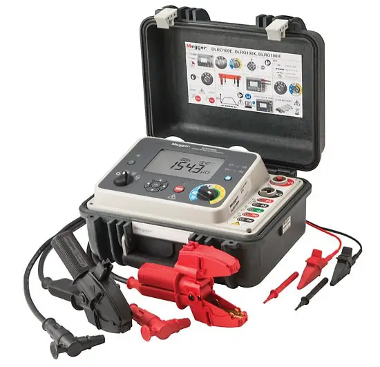
Insulation Resistance Tester Megger
This test is performed at or above the rated voltage to determine if there are low resistance paths to the ground or between winding to winding as a result of winding insulation deterioration.

The test measurement values are affected by variables such as temperature, humidity, test voltage, and size of the transformer. 

This test should be conducted before and after repair or when maintenance is performed. The test data should be recorded for future comparative purposes. The test values should be normalized to 20°C for comparison purposes. 

Insulation resistance test is conducted in most of the substation equipment is high and medium voltage substations.

The general rule of thumb that is used for acceptable values for safe energization is 1 MΩ per 1000 V of applied test voltage plus 1 MΩ. Sample resistance values of good insulation systems are shown in Table. 

Recommended Minimum Insulation Resistance for Transformer Winding

Rated Voltage
( kV)
IR value in MΩ
30°C
40°C
50°C
60°C
66 and above
600
300
150
75
33
500
250
125
65
11 & 6.6
400
200
100
50
Below 6.6
200
100
50
25
Note: As a rough guide, the Megger values should be 2 meg. Ohms for every rating at 60°C for 11 KV and above. The Megger values double itself for every 10°C fall in temperature.

The procedure of IR Test:

The procedure of the insulation resistance test are given below
  1. First, disconnect all the line and neutral terminals of the transformer.
  2. Megger leads to be connected to LV and HV bushing studs to measure Insulation Resistance IR value in between the LV and HV windings. 
  3. Megger leads to be connected to HV bushing studs and transformer tank earth point to measure Insulation Resistance IR value in between the HV windings and earth. 
  4. Megger leads to be connected to LV bushing studs and transformer tank earth point to measure Insulation Resistance IR value in between the LV windings and earth. 
It is unnecessary to perform the insulation resistance test of transformer per phase-wise in a three-phase transformer.

Insulation Resistance values are taken between the windings collectively as because all the windings on the HV side are internally connected together to form either star or delta. Also, all the windings on the LV side are internally connected together to form either star or delta. 

Related: Tests and Tag Courses

 Measurements are to be taken as follows :

  • For Auto-transformer
    • HV-IV to LV, 
    • HV-IV to E,
    • LV to E
  • For Two winding transformer
    • HV to LV,
    • HV to E,
    • LV to E
  • For Three winding transformer
    • HV to IV,
    • HV to LV,
    • IV to LV,
    • HV to E,
    • IV to E,
    • LV to E
  • Share:
Admin bar avatar
Tesla Edison
Tesla is an Electrical Engineer, Physicist and an Inventor in making. He is a good writer and author of many courses and articles published in this site.

Previous post

Three Phase Transformer Interconnections
August 16, 2014

Next post

Characteristics of DC Compound Generator
August 19, 2014

    1 Comment

  1. Mariam Anna
    May 30, 2019
    Reply

    What is the minimum acceptable value of insulation resistance?
    Please give me an answer.

Leave A Reply Cancel reply

Your email address will not be published. Required fields are marked *

Login with your site account

Connect with

FacebookGoogleLinkedIn

logo


Lost your password?

Not a member yet? Register now

Recent Articles

  • Going Beyond Theory And Books: High-performance Liquid Chromatography
  • How to Select an Electronic Contract Manufacturing Partner
  • 7 FE Electrical and Computer Practice Problems with Solutions
  • Sinusoids and Phasors
  • 2 Important Distribution Transformer Testing Methods
For Advertisements Contact
[email protected]

Copyright © 2020 Study Electrical, Inc.

© StudyElectrical.Com 2020

Connect with

Login with Facebook Login with Google Login with LinkedIn

logo

Login with your site account

Connect with

FacebookGoogleLinkedIn

logo


Lost your password?

Not a member yet? Register now

Register a new account

Connect with

FacebookGoogleLinkedIn

logo


Are you a member? Login now