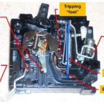
The hydraulic magnetic circuit breaker is a specialized electrical switchgear device that integrates overload and fault protection within a single mechanism, eliminating the need for separate thermal and magnetic mechanisms.
It is particularly useful in environments where traditional thermal protection circuit breaker may fail due to extreme temperatures or moisture conditions. Low temperatures might prevent thermal protection from tripping, while high temperatures might make it trip accidentally.
To overcome these limitations, an alternative solution like the hydraulic magnetic circuit breaker becomes essential.
Key Features:
- Operational Range: Available for a wide range of operational voltages up to 240 volts and frequencies of both 50 Hz and 60 Hz.
- Variety: Offered in one, two, and three-pole versions to suit various circuit configurations.
- Current Ratings: Typically below 100 amperes, comparable to miniature circuit breakers.
Construction
The construction and different parts of hydraulic magnetic circuit breaker is given below.
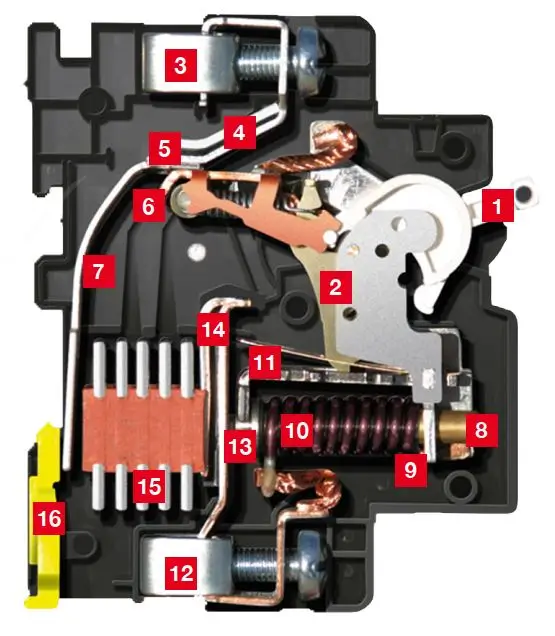
1. Handle
2. Mechanism assembly
3. Line terminal
4. Fixed contact
5. Contact tips
6. Moving contact
7. Arc runner line side
8. Hermetically sealed tube
9. Magnetic frame
10. Solenoid coil
11. Armature
12. Load terminal
13. Pole piece
14. Arc runner load side
15. Arc grids
16. Clip-in springs
The construction of a Hydraulic Magnetic Circuit Breaker involves several key components:
- Handle: Provides manual operation for switching the circuit breaker on or off.
- Mechanism Assembly: Contains the internal mechanism responsible for tripping the breaker in case of overload or fault.
- Line Terminal: Connects the circuit breaker to the incoming power supply line.
- Fixed Contact: Stationary contact point within the breaker for conducting electrical current.
- Contact Tips: Points of electrical contact between the moving and fixed contacts, ensuring current flow.
- Moving Contact: Mobile contact point that engages and disengages with the fixed contact during operation.
- Arc Runner Line Side: Component designed to guide and manage electrical arcs generated during circuit interruption on the line side of the breaker.
- Hermetically Sealed Tube: Enclosure containing the damping fluid, ensuring consistent performance across various temperatures.
- Magnetic Frame: Provides structural support and alignment for the solenoid coil and armature.
- Solenoid Coil: Generates a magnetic field when current passes through, contributing to the operation of the breaker mechanism.
- Armature: Movable component within the solenoid coil assembly, influenced by magnetic forces to trip the breaker.
- Load Terminal: Connects the circuit breaker to the outgoing load circuit.
- Pole Piece: Component that directs and concentrates the magnetic flux generated by the solenoid coil.
- Arc Runner Load Side: Component similar to the arc runner line side, but located on the load side of the breaker.
- Arc Grids: Grid-like structures positioned to control and extinguish electrical arcs produced during circuit interruption.
- Clip-in Springs: Springs used for securing and positioning various components within the breaker assembly.
These components work together to provide reliable overload and fault protection in hydraulic magnetic circuit breakers, ensuring safe and efficient operation of electrical systems.
Working Principle
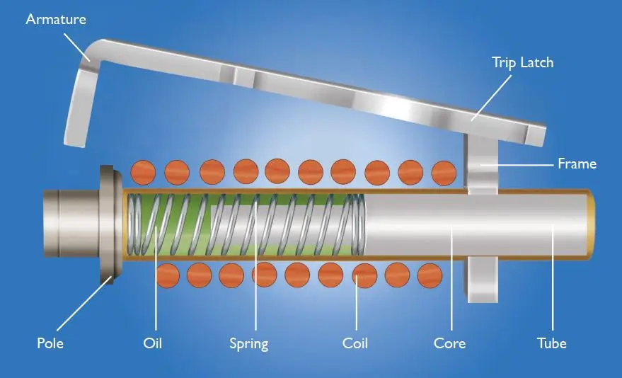
Hydraulic magnetic circuit breakers provide both overload and fault protection with a single mechanism:
- a solenoid coil is combined with
- a spring-loaded actuator inside a cylinder filled with a dampening fluid,
Hence the name of hydraulic magnetic circuit breaker.
Hydraulic-Magnetic Technology
Hydraulic-magnetic circuit breakers operate based on the magnetic force generated by the flow of load current through a solenoid coil connected in series. Here’s how they function:
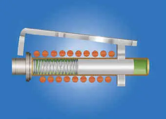
Normal Operation:
- At or below the circuit breaker’s rated current, the magnetic flux in the solenoid is insufficient to attract the core towards the pole piece due to the opposing force of the spring.
- Consequently, the circuit breaker remains closed, and the circuit remains energized.
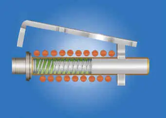
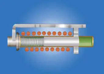
Overload:
- When an overload occurs, where the current exceeds the breaker’s rating, the magnetic flux in the solenoid starts pulling the core towards the pole piece.
- The movement of the core is regulated by the hydraulic fluid, creating a controlled time delay proportional to the overload magnitude. This delay allows for temporary overloads, like motor startups, to pass without tripping the breaker.
- If the overload persists, the core eventually reaches the pole piece, reducing the reluctance of the magnetic circuit.
- As a result, the armature is attracted to the pole piece with enough force to collapse the latch mechanism, tripping the breaker.
- The contacts separate, interrupting the current flow, and the core returns to its rest position.
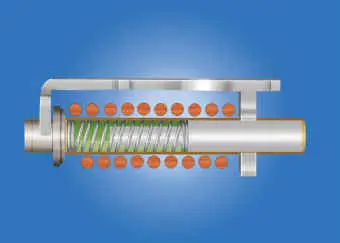
Short Circuit:
- In cases of high overloads or short circuits, the magnetic flux from the coil can instantly attract the armature to the pole face, even before the core moves.
- This instantaneous trip feature is present in the breaker’s characteristic curve.
- Unlike thermal circuit breakers, the trip point of hydraulic-magnetic breakers remains unaffected by ambient temperature.
- After tripping, the breaker can be immediately re-closed without requiring a cooldown period.
Customization:
- Due to the operating principle, hydraulic-magnetic circuit breakers can be designed with various time-current characteristics to suit specific applications.
Hydraulic-magnetic circuit breakers offer reliable protection against overload and short circuit conditions, with the added benefit of consistent performance across a range of temperatures.
Hydraulic Magnetic Circuit Breaker vs Thermal Magnetic Circuit Breaker
Here’s a breakdown of the main differences between hydraulic-magnetic circuit breakers and thermal-magnetic circuit breakers:
- Overload Protection Mechanism:
- Thermal-Magnetic Circuit Breakers: Use a bimetallic strip that expands and contracts in response to temperature changes caused by overload currents. The strip interrupts the circuit when it expands sufficiently.
- Hydraulic-Magnetic Circuit Breakers: Employ a solenoid coil and a dampened spring actuator to provide time-delayed disconnection in case of overload. The solenoid coil generates a magnetic field that attracts a core towards a pole piece, causing the mechanism to trip after a controlled time delay.
- Fault Protection Mechanism:
- Both Types: Share the same working principle for fault protection. During a fault like a short circuit or line-to-ground fault, very high currents induce a strong magnetic field in the solenoid coil. This magnetic field causes the contacts to open, interrupting the circuit.
- Hydraulic-Magnetic Breakers: The damping cylinder does not cause a time delay in this scenario, as the current and induced magnetic field are extremely strong, leading to an instantaneous trip.
- Function and Application:
- Both Types: Serve the same purpose of providing overload and fault protection in electrical circuits.
- Thermal-Magnetic Breakers: Suitable for use in applications where temperature variations are not a concern.
- Hydraulic-Magnetic Breakers: Preferred in environments where temperature extremes might affect the performance of thermal protection mechanisms.
- Specialized Characteristics:
- Each type of breaker has specialized characteristics that make it suitable for specific applications.
- Thermal-magnetic breakers are commonly used in standard electrical installations where temperature is not expected to vary significantly.
- Hydraulic-magnetic breakers are recommended for environments with extreme temperatures or where consistent performance across a wide temperature range is required.
| Feature | Thermal-Magnetic Circuit Breakers | Hydraulic-Magnetic Circuit Breakers |
|---|---|---|
| Overload Protection Mechanism | Bimetallic strip expands and contracts with temperature changes caused by overload currents, interrupting the circuit when sufficiently expanded. | Solenoid coil and dampened spring actuator provide time-delayed disconnection in case of overload. The solenoid coil generates a magnetic field that attracts a core towards a pole piece, causing the mechanism to trip after a controlled time delay. |
| Fault Protection Mechanism | Very high currents induce a strong magnetic field in the solenoid coil, causing the contacts to open and interrupting the circuit. | Similar to thermal-magnetic breakers, very high currents induce a strong magnetic field in the solenoid coil, causing the contacts to open and interrupting the circuit. The damping cylinder does not cause a time delay in this scenario, leading to an instantaneous trip. |
| Function and Application | Provides overload and fault protection in electrical circuits. | Serves the same purpose of providing overload and fault protection in electrical circuits. |
| Suitability for Temperature Variations | Suitable for use in applications where temperature variations are not a concern. | Preferred in environments where temperature extremes might affect the performance of thermal protection mechanisms. |
| Specialized Characteristics | Relies on temperature-sensitive bimetallic strips for overload protection. | Uses solenoid coils and dampened spring actuators for overload protection, making them more suitable for applications where temperature variations might affect performance. |
Applications
Application of hydraulic magnetic circuit breakers are given below.
- Marine Environments: Ideal for boats due to their resistance to moisture and temperature extremes.
- Land Transportation: Used in vehicles subject to heat and external temperature fluctuations.
- Electric Generator Rooms: Ensures backup power is not accidentally interrupted due to thermal protection failure.
- Outdoor Locations: Suitable for electric distribution boxes in harsh climates.
- Industrial Settings: Provides reliable protection in environments with high temperatures.
- Sensitive Equipment: Used where precise current sensing is required, and thermal protection may not be adequate.
Summary
In summary, hydraulic magnetic circuit breakers offer robust protection against overloads and faults in environments where traditional thermal protection may be unreliable. Their versatility and reliability make them suitable for a wide range of applications, particularly those with challenging environmental conditions.