HVDC stands for High Voltage Direct Current. An HVDC electric power transmission system uses direct current for the bulk transmission of electrical power, in contrast with the more common alternating current systems.
For long-distance distribution, HVDC systems are less expensive and suffer lower electrical losses. For shorter distances, the higher cost of DC conversion equipment compared to an AC system may be warranted where other benefits of direct current links are useful.
When HVDC Started?
The HVDC (high voltage DC) transmission made the modest beginning in 1954 when a 100 kV, 20 MW DC-link was established between the Swedish mainland and the island of Gotland.
The latest technology in HVDC system is to use LTT’s (Light triggered thyristors) or GTO’s (Gate turn off) or IGBT’s (Insulated gate bipolar transistor). Control is obtained by using the VSC (Voltage source converter) using PWM (Pulse width modulation) technique.
Components of HVDC Transmission System
The main elements of an HVDC system are:
-
- Converter unit
- Converter transformer
- AC filters & Capacitor banks
- DC filters
- Reactive Power source
- Smoothing Reactor
- DC Switchgear
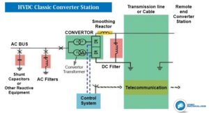
1. HVDC Converter Station
An HVDC converter station uses thyristor valves to perform the conversion from AC to DC and vice versa. The valves are normally arranged as a 12- pulse converter.
The valves are connected to the AC system by means of converter transformers. The valves are normally placed in a building and the converter transformers are located just outside.
2. HVDC Converter Transformer

The converter transformers are the heaviest equipment in an HVDC converter station. Single units can often have a total weight of 200 – 550 tons.
The converter transformer serves several functions:
- Supply of AC voltages in two separate circuits with a relative phase shift of 30 electrical degrees for reduction of low order harmonics, especially the 5th and 7th harmonics.
- Act as a galvanic barrier between the AC and DC systems to prevent the DC potential to enter the AC system.
- Reactive impedance in the AC supply to reduce short circuit currents and to control the rate of rise in valve current during commutation.
- Voltage transformation between the AC supply and the HVDC system.
The HVDC converter transformer can be built as three-phase units or as single-phase units depending on voltage and power rating. When built as three-phase transformers there is generally one unit with the valve winding arranged for star connection and the other unit for delta connection. In single-phase design, the two-valve windings are generally built on the same transformer unit.
Design-wise the internal voltage distribution from the DC-voltages on the transformer valve terminals will need a different insulation build-up as compared to the insulation system in a conventional transformer.
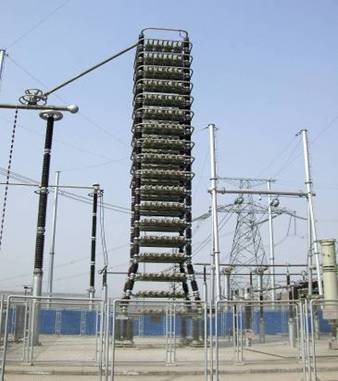
Converter Valve
The quadruple valve structure is suspended from the ceiling of the valve hall via porcelain insulators. At the top and bottom of the structure, a metallic framework ensures the mechanical stability of the valves. Between the frameworks, the different levels in the valve are mechanically fixed by means of threaded epoxy rods.
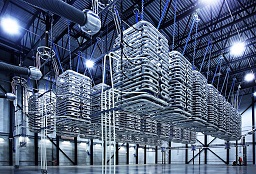
Thyristor valves are the heart of the HVDC conversion process. Modern valves have an excellent performance record and very small losses. The thyristor valves do the actual conversion from AC to DC or vice versa.
The basic circuit used is the Graetz bridge consisting of six valve functions, but in order to eliminate the largest harmonics, two such bridges are connected in series forming a 12-pulse converter.
The valves are normally located in a valve building and arranged as three structures (quadruple valves) suspended from the ceiling of the valve hall, but other arrangements do exist.
AC Filters
Conventional HVDC converters always have a demand for reactive power. At normal operation, a converter consumes reactive power in an amount that corresponds to approximately 50 % of the transmitted active power.
The least costly way to generate reactive power is in shunt connected capacitor banks. Some of these capacitor banks can then be combined with reactors and resistors to form filters providing low impedance paths for the harmonics in order to limit them from entering into the AC network.
Active DC filters
the DC circuit canceling the DC side harmonics coming from the HVDC converter. The amplifier is controlled by a high-speed digital signal process controller.
For overhead line transmissions, it is normally necessary to install additional filter circuits between the pole bus (outside the smoothing reactor) and the neutral bus.
HVDC Smoothing Reactor

The main objectives of the reactor are:
- To smooth the ripple current in DC
- To reduce the risk of commutation failures by limiting the rate of rising of the DC line current at transient disturbances in the AC or DC systems.
- Prevention of resonance in the DC circuit.
- Reducing harmonic currents including limitation of telephone interference
- Air-insulated smoothing reactor
- Oil-insulated (filled) smoothing reactor
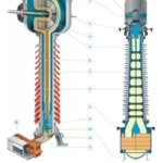
Typical layout of HVDC transmission system
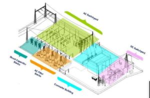
The figure shows the typical layout of the HVDC substation which is having AC switchyard and DC switchyard and converter building in between. And this converter building contains a converter transformer, converter bridge, etc. The AC filters are provided near the AC switchyard for the compensation.

good explaination
Great content. Learned about HVDC from your article. Thank you