• Home
  • Courses
  • Machines
    • Transformer
    • AC Motors
      • Induction Motor
      • Synchronous Motor
    • DC Motor
    • DC Generator
  • Power System
    • Circuit Breaker
    • Switchgear
    • Substation
    • Control System
    • Measurement
  • Electronics
  • Blog
  • Contact
    • Contact Us
    • Privacy Policy
Have any question?
[email protected]
RegisterLogin
StudyElectrical.Com
  • Home
  • Courses
  • Machines
    • Transformer
    • AC Motors
      • Induction Motor
      • Synchronous Motor
    • DC Motor
    • DC Generator
  • Power System
    • Circuit Breaker
    • Switchgear
    • Substation
    • Control System
    • Measurement
  • Electronics
  • Blog
  • Contact
    • Contact Us
    • Privacy Policy

Electronics

Constant Current Driver Design based on LM317

  • Categories Electronics, Projects
Constant 2BCurrent 2BDriver 2BDesign 2Bbased 2Bon 2BLM317

Using a resistor to limit the current can be used for small LEDs. For such low power LEDs, where the supply current is not critical it works okay. 

But for high-power Light Emitting Diodes, a better way is to use the Constant Current Driver.

As the name suggests, the constant current driver will supply the same current whatever voltage it is supplied with and whatever the forward voltage of the LED. You just set the current and that is how much current will flow through the high-power LED.

A very useful IC that is often used for this purpose is the LM317. This IC is primarily intended as an adjustable voltage regulator, but can easily be adapted for use in regulating current.

Design of Constant Current Driver

The figure below shows the schematic diagram for regulating the current to a high-power LED.

Constant 2BCurrent 2BDriver 2BDesign 2Bbased 2Bon 2BLM317

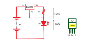
The LM317 is very easy to use in a constant current mode. It will always strive to keep its output voltage at exactly 1.25V above whatever voltage the Adj (adjust) pin is at.

The LED we are going to use is a 1W white light LED. It has an If (forward current) of 300mA and a Vf (forward voltage) of 3.4V.

The formula for calculating the right value for R for use with the LM317 is:

R = 1.25V / I 
so in this case, R = 1.25 / 0.3 = 4.2Ω
 
If we used a standard resistor value of 4.7Ω, then this would reduce the current to:
 
I = 1.25V / 4.7Ω = 266 mA
 
Checking the power rating for the resistor, the LM317 will always have 1.25V between Out and Adj. So:
P = V × I = 1.25V × 266mA = 0.33W

A half-watt resistor will, therefore, be fine.

The LM317 also needs its input to be about 3V higher than its output to guarantee 1.25V between Adj and the output.

constant 2Bcurrent 2BdriverThis means that a 6V battery would not be quite high enough because the forward voltage is 3.4V. However, we could drive the circuit using a 9V battery or even a 12V power supply without modification, since whatever the input voltage, the current will always be limited to about 260mA.

A quick calculation of the power consumed by the LM317 will reassure us that we are not going to come near exceeding its maximum power rating.

For a 9V battery, the voltage between In and Out will be 

9 – (1.25 + 3.4) = 4.35V. 

The current is 260mA, so the power is: 

4.35 × 0.26 = 1.13W.

According to its datasheet, the maximum power handling capability of the LM317 is 20W, and it can cope with a current of up to 2.2A for a supply voltage of less than 15V. So we are fine.

Related Articles

  • Automatic Light Controller arduino
    Arduino based Automatic Light Controller

    The automatic light controller offers energy saving and convenience in the areas with a photosensor…

  • electric current on human body
    Effect of Electric Current on Human Body at 50 Hz

    Each year in France, for example, 200 people die of electrocution and 500 suffer serious…

  • Current
    What Are Current, Resistance and Voltage?

    Voltage, current, and resistance are three properties that are fundamental to almost everything you will…

  • Current Transformer construction
    Current Transformers - Windings and Rated Insulation Levels

    A current transformer is an instrument transformer in which the current ratio is within the…

  • Types-of-Electric-current
    Types of Electric Current - Steady (DC), Varying & Alternating (AC) Current

    The directed flow of free electrons (or charge) is called the electric current. The electric…

  • Construction of High Voltage Current Transformer
    Basic Types of Current Transformers

    Current Transformers (CT’s) are instrument transformers that are used to supply a reduced value of…

  • Share:
author avatar

Previous post

What Jobs Electrical Engineers Do? | Roles and Responsibilities

Next post

Practical Transformer on No Load

You may also like

dc voltage source
What is a Voltage Source? | DC and AC Voltage Sources Explained
arduino program structure
How to Structure an Arduino Program?
electrolytic capacitors
Electrolytic Capacitor – Types, Construction, Polarity and Leakage Current

    1 Comment

  1. KiaJed
    June 17, 2019
    Reply

    I am going to make it. Thanks for explaining

Leave A Reply Cancel reply

Your email address will not be published. Required fields are marked *

Search Here

From Blog

Open Loop and Closed Loop Control System
Open Loop and Closed Loop Control System (4 Practical Examples Included)
Teach Yourself Electricity and Electronics
Electromagnetics Lecture Notes PDF
[PDF] Electromagnetism Lecture Notes – University of Cambridge
Role of commercial electrician
Roles of a Commercial Electrician

Categories

  • Alternator
  • Arduino
  • Basic Electrical
  • Battery
  • Books
  • Cables
  • Capacitor
  • Career
  • Circuit Breaker
  • Control System
  • DC Generator
  • DC Motor
  • Electric Vehicles
  • Electrical Circuits
  • Electrical Machines
  • Electrical Relays
  • Electrical Safety
  • Electronics
  • Embedded System
  • Exams
  • Generation
  • Guest Post
  • HVDC
  • Instrumentation
  • Interview Questions
  • Locomotives
  • Measurement
  • Microcontroller
  • Objective Questions
  • PCB
  • PLC
  • Power System
  • Projects
  • Signals and Systems
  • Single Phase Motors
  • Substation
  • Switchgear
  • Synchronous Motor
  • Three Phase Induction Motor
  • Transformer
  • Transmission Line
  • Uncategorized

Copyright © 2021 Study Electrical, Inc.

© StudyElectrical.Com 2021

Login with your site account

Lost your password?

Not a member yet? Register now

Register a new account

Are you a member? Login now