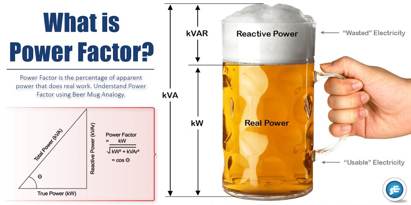
 Simply stated, the Power Factor is the percentage of Apparent Power that does real work.
- kW – Working Power (also called Actual Power or Active Power or Real Power):- It is the power that actually powers the equipment and performs useful work.
- kVAR – Reactive Power:- It is the power that magnetic equipment (transformer, induction motor, and relay) needs to produce the magnetizing flux.
- kVA – Apparent Power:- It is the “vectorial summation” of KVAR and KW.
Understanding Power Factor using Beer Mug Analogy
Let’s say you are at the park and it is a really hot day. You order up a mug of beer.

- The thirst-quenching portion of your beer is represented by KW. This is usable power.
- Along with your beer comes a little bit of foam. (And that foam just doesn’t quench your thirst.) This foam is represented by KVAR. This part is wasted power.
- The total contents of your mug, KVA, is this summation of KW (the beer) and KVAR (the foam).
Also Read: Horse Rail Analogy
- The more foam you have (the higher the percentage of KVAR), the lower your ratio of KW (beer) to KVA (beer plus foam). Thus, the lower your power factor.
- The less foam you have (the lower the percentage of KVAR), the higher your ratio of KW (beer) to KVA (beer plus foam). In fact, as your foam (or KVAR) approaches zero, your power factor approaches 1.0.
Power Triangle

- KVAR would be very small (foam would be approaching zero)
- KW and KVA would be almost equal (more beer; less foam)
So, In order to have an “efficient” system, we want the power factor to be as close to 1.0 as possible.
A power factor of one or “unity power factor” is the goal of any electric utility company.
It is because if the power factor is less than one, they have to supply more current to the user for a given amount of power use. In so doing, they incur more line losses.
What Causes Low Power Factor?
Great, now we understood what power factor is.
Recently I found that the power factor in my factory is very low. I was thinking what wrong I did to cause this?
Since power factor is defined as the ratio of KW to KVA, we see that low power factor results when KW is small in relation to KVA.
Remembering our beer mug analogy, this would occur when KVAR (foam) is large.
What causes a large KVAR in a system? The answer is Inductive Loads.
Inductive loads (which are sources of Reactive Power) include:
- Transformers
- Induction motors
- Induction generators (windmill generators)
- High-intensity discharge (HID) lighting
These inductive loads constitute a major portion of the power consumed in industrial complexes.
Reactive power (KVAR) required by inductive loads increases the amount of apparent power (KVA) in your distribution system.
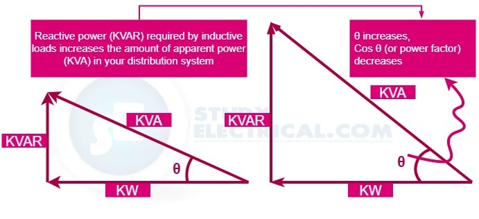
This increase in reactive and apparent power results in a larger angle θ (measured between KW and KVA). Recall that, as θ increases, cosine θ (or power factor) decreases.
So, inductive loads (with large KVAR) result in low power factor.
Why Should I Improve My Power Factor?
Okay. So I’ve got inductive loads at my facility that is causing my power factor to be low. Why should I want to improve it?
You want to improve your power factor for several different reasons. Some of the benefits of improving your power factor include:
1. Lower Utility Fees
Improving the power factor can lower the utility bill by
- Reducing peak KW billing demand
- Eliminating the power factor penalty
Utilities usually charge customers an additional fee when their power factor is less than 0.95 (some below 0.85). You can avoid this additional fee by increasing your power factor.
2. Increased system capacity and Reduced system losses
By adding capacitors (KVAR generators) to the system, the power factor is improved and the KW capacity of the system is increased.
Uncorrected power factor causes power system losses in your distribution system. By improving your power factor, these losses can be reduced.
With the current rise in the cost of energy, increased facility efficiency is very desirable. And with lower system losses, you are also able to add additional load to your system.
3. Increased voltage level and Efficiency
Improved power factor can bring an increased voltage level in your electrical system and more efficient motors.
As mentioned above, the uncorrected power factor causes power system losses in your distribution system.
So, by raising your power factor, you will minimize these voltage drops along with feeder cables and avoid related problems. Your motors will run cooler and be more efficient, with a slight increase in capacity and starting torque.
How Do I Correct (Improve) My Power Factor?
How do I go about improving (i.e., increasing) my power factor?
We have seen that sources of Reactive Power (inductive loads) decrease power factor:
- Transformers
- Induction motors
- Induction generators (windmill generators)
- High-intensity discharge (HID) lighting
Similarly, consumers of Reactive Power increase power factor:
- Capacitors
- Synchronous generators (utility and emergency)
- Synchronous motors
Thus, it comes as no surprise that one way to increase the PF is to add capacitors to the system. This and other ways of increasing power factor are listed below:
1. Installing capacitors (KVAR Generators)
Installing capacitors decrease the magnitude of reactive power (KVAR or foam), thus increasing your power factor.
Here is how it works,
Reactive power (KVAR) caused by inductive loads, always acts at a 90-degree angle to working power (KW).
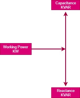
Inductance and capacitance react 180 degrees to each other. Capacitors store KVAR and release energy opposing the reactive energy caused by the inductor.
The presence of both a capacitor and inductor in the same circuit results in the continuous alternating transfer of energy between the two.
Thus, when the circuit is balanced, all the energy released by the inductor is absorbed by the capacitor.
2. Minimizing operation of idling or lightly loaded motors.
We already talked about the fact that low PF is caused by the presence of induction motors.
But, more specifically, low power factor is caused by running induction motors lightly loaded.
3. Avoiding operation of equipment above its rated voltage.
Another method of improving the PF is to avoid operating equipment above their rated voltage.
4. Replacing standard motors as they burn out with energy-efficient motors.
Even with energy-efficient motors, power factor is significantly affected by variations in load.
A motor must be operated near its rated load in order to realize the benefits of a high power factor design.