• Home
  • Courses
  • Machines
    • Transformer
    • AC Motors
      • Induction Motor
      • Synchronous Motor
    • DC Motor
    • DC Generator
  • Power System
    • Circuit Breaker
    • Switchgear
    • Substation
    • Control System
    • Measurement
  • Electronics
  • Blog
  • Contact
    • Contact Us
    • Privacy Policy
Have any question?
[email protected]
RegisterLogin
StudyElectrical.Com
  • Home
  • Courses
  • Machines
    • Transformer
    • AC Motors
      • Induction Motor
      • Synchronous Motor
    • DC Motor
    • DC Generator
  • Power System
    • Circuit Breaker
    • Switchgear
    • Substation
    • Control System
    • Measurement
  • Electronics
  • Blog
  • Contact
    • Contact Us
    • Privacy Policy

Electrical Machines

Working Principle of Transformer

  • Categories Electrical Machines, Transformer
Differences between Power Transformer and Distribution Transformer

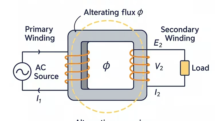
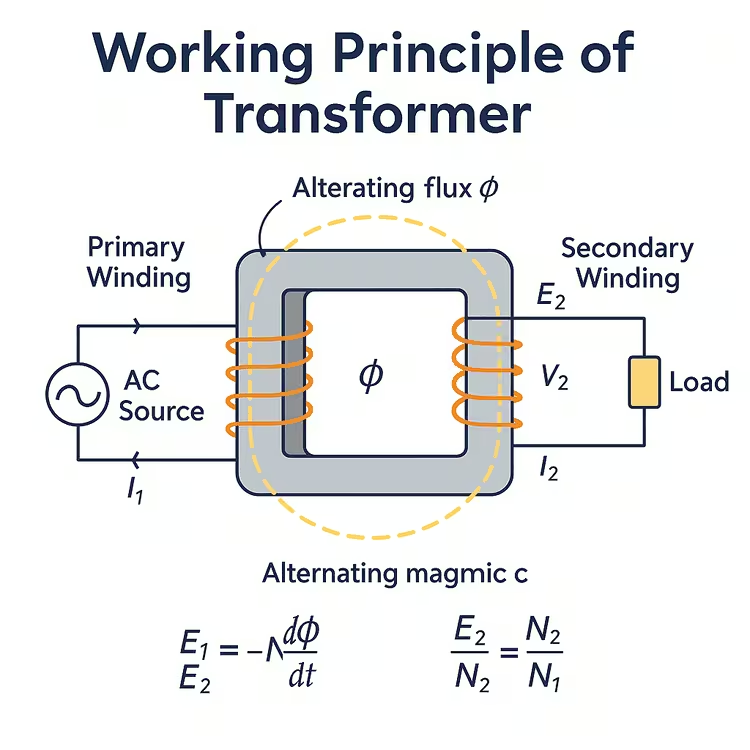
A transformer is a static piece of equipment used either for raising or lowering the voltage of an AC supply with a corresponding decrease or increase in current. It essentially consists of two windings on a common laminated magnetic core.

  • Primary Winding – AC source is connected to this winding.
  • Secondary Winding – Load is connected to this winding.

The alternating voltage V1 whose magnitude is to be changed is applied to the primary. Depending upon the number of turns of the primary (N1) and secondary (N2), an alternating e.m.f. E2 is induced in the secondary.

This induced e.m.f. E2 in the secondary causes a secondary current I2. Consequently, terminal voltage V2 will appear across the load. 

Working of Transformer

  • If V2 > V1 , it is called a step-up transformer. 
  • If V2 < V1 , it is called a step-down transformer.

When an alternating voltage V1 is applied to the primary, an alternating flux φ is set up in the core. This alternating flux links both the windings and induces e.m.f.s E1 and E2 in them according to Faraday’s laws of electromagnetic induction. The e.m.f. E1 is termed as primary e.m.f. and e.m.f. E2 is termed as secondary e.m.f.

E1 = –N1 (dφ/dt)

E2 = –N2 (dφ/dt)

∴ E2/E1 = N2/N1

Note that magnitudes of E2 and E1 depend upon the number of turns on the secondary and primary respectively. 

If N2 > N1, then E2 > E1 (or V2 > V1) and we get a step-up transformer. 

On the other hand, if N2 < N1, then E2 < E1 (or V2 < V1) and we get a step-down transformer. 
 
If the load is connected across the secondary winding, the secondary e.m.f. E2 will cause a current I2 to flow through the load. Thus, a transformer enables us to transfer a.c. power from one circuit to another with a change in voltage level.

The following points may be noted carefully:

  • The transformer action is based on the laws of electromagnetic induction.
  • There is no electrical connection between the primary and secondary. The a.c. power is transferred from primary to secondary through the magnetic flux.
  • There is no change in frequency i.e., output power has the same frequency as the input power.

The losses that occur in a transformer are:

  1. core losses – eddy current and hysteresis losses
  2. copper losses—in the resistance of the windings

In practice, these losses are very small so that output power is nearly equal to the input primary power. In other words, a transformer has very high efficiency.

[HDquiz quiz = “6326”]

HDquiz quiz = “6326”

Related Articles

  • Three Phase Transformer Connections
    Three Phase Transformer Interconnections

    The phase windings of three-phase transformers are interconnected to give a three-phase, three-or four-wire supply…

  • ideal 2Btransformer 2Bphasor 2Bdiagram
    Ideal Transformer and Practical Transformer

    Ideal Transformer An ideal transformer is one that has no winding resistance no leakage flux…

  • DC Motor working 1
    Working Principle of DC Motor

    A DC motor is an electrical machine that converts electrical energy into mechanical energy.  The…

  • Rectifier Transformers
    Rectifier Transformer - Working Principle and Application

    What is the Rectifier Transformer? Rectifier transformers are different from normal power and distribution transformers…

  • working principle of alternator
    Working Principle of Alternator

    The machine which produces 3 phase power from mechanical power is called an alternator or…

  • Current 2BTransformer 2BConstruction 2Bor 2BCircuit 2BDiagram 2Band 2BSymbol
    Current Transformer (CT) - Construction and Working Principle

    A current transformer (CT) is a type of transformer that is used to measure AC…

  • Share:
author avatar

Previous post

Electrical and Mechanical Noise in Motors

Next post

Testing of DC Machines (DC Motor and DC Generator)

You may also like

methods of magnetizing steel bar
3 Methods of Magnetizing a Steel Bar
Three Phase Transformer
Three-Phase Transformer – Basics and Connection Methods
Open Delta Connection in Transformer
Open Delta (V-V) Connection of Transformers

    6 Comments

  1. biraj j. thapa
    September 23, 2019
    Reply

    it’s hard to find the content i mean table of content from the basic to advanced level not provided, some random topics are given which makes us difficult to develop concepts from the beginning and move forward gradually…

  2. Henry Killingsworth
    January 25, 2022
    Reply

    It was really interesting when you talked about how transformers are used to lower or raise the voltage of an AC supply. It seems like you would want to lower the power of electrical currents that are going into a home. That way all of the electrical outlets and devices in a home aren’t blown out by a strong current. http://tarbellassociates.com/territories-and-lines/

  3. NOMAN ZAHOOR
    May 7, 2022
    Reply

    great content but people should visit https://www.eengineer.in/transformer-definition-working-principle-diagram-types/ for a better infographic explanation.

Leave A Reply Cancel reply

Your email address will not be published. Required fields are marked *

Search Here

From Blog

substation earthing
Substation Earthing System Design
working%2Bof%2Bmoving%2Bcoil
Animated Video – Working of Moving Coil Instruments
working%2Bof%2Bmoving%2Bcoil
Section-wise Preparation Tips for JEE Mains Paper-1 Exam
Brass Bushing
The efficient role of Brass Bushing

Categories

  • Alternator
  • Arduino
  • Basic Electrical
  • Battery
  • Books
  • Cables
  • Capacitor
  • Career
  • Circuit Breaker
  • Control System
  • DC Generator
  • DC Motor
  • Electric Vehicles
  • Electrical Circuits
  • Electrical Machines
  • Electrical Relays
  • Electrical Safety
  • Electronics
  • Embedded System
  • Exams
  • Generation
  • Guest Post
  • HVDC
  • Instrumentation
  • Interview Questions
  • Locomotives
  • Measurement
  • Microcontroller
  • Objective Questions
  • PCB
  • PLC
  • Power System
  • Projects
  • Signals and Systems
  • Single Phase Motors
  • Substation
  • Switchgear
  • Synchronous Motor
  • Three Phase Induction Motor
  • Transformer
  • Transmission Line
  • Uncategorized

Copyright © 2021 Study Electrical, Inc.

© StudyElectrical.Com 2021

Login with your site account

Lost your password?

Not a member yet? Register now

Register a new account

Are you a member? Login now