• Home
  • Courses
  • Machines
    • Transformer
    • AC Motors
      • Induction Motor
      • Synchronous Motor
    • DC Motor
    • DC Generator
  • Power System
    • Circuit Breaker
    • Switchgear
    • Substation
    • Control System
    • Measurement
  • Electronics
  • Blog
  • Contact
    • Contact Us
    • Privacy Policy
Have any question?
[email protected]
RegisterLogin
StudyElectrical.Com
  • Home
  • Courses
  • Machines
    • Transformer
    • AC Motors
      • Induction Motor
      • Synchronous Motor
    • DC Motor
    • DC Generator
  • Power System
    • Circuit Breaker
    • Switchgear
    • Substation
    • Control System
    • Measurement
  • Electronics
  • Blog
  • Contact
    • Contact Us
    • Privacy Policy

Capacitor

Electrolytic Capacitor – Types, Construction, Polarity and Leakage Current

  • Categories Capacitor, Electronics
electrolytic capacitors

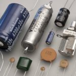
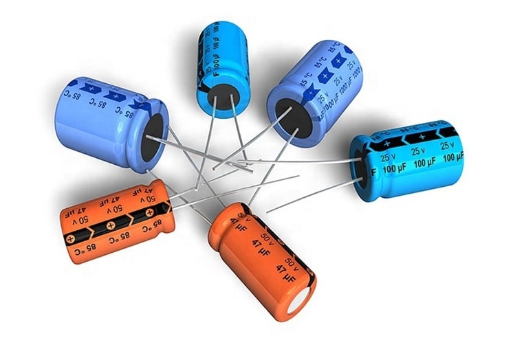
Electrolytic capacitors are one of the most commonly used types of capacitor. Their capacitance values range from about 1 μF to 6800 μF. Electrolytic capacitors are more popular because the electrolytes used in it provide the most capacitance in the smallest space with the least cost.

electrolytic capacitors
Electrolytic capacitors

Table of Contents

  • Construction of Electrolytic Capacitor
  • Electrolytic Capacitor Polarity
    • Leakage Current
  • Nonpolarized Electrolytic Capacitor
    • Related Articles

Construction of Electrolytic Capacitor

In this section, you will learn the construction of an aluminium-foil type electrolytic capacitor.

Internal electrodes
Internal Electrodes in an aluminium foil electrolytic capacitor

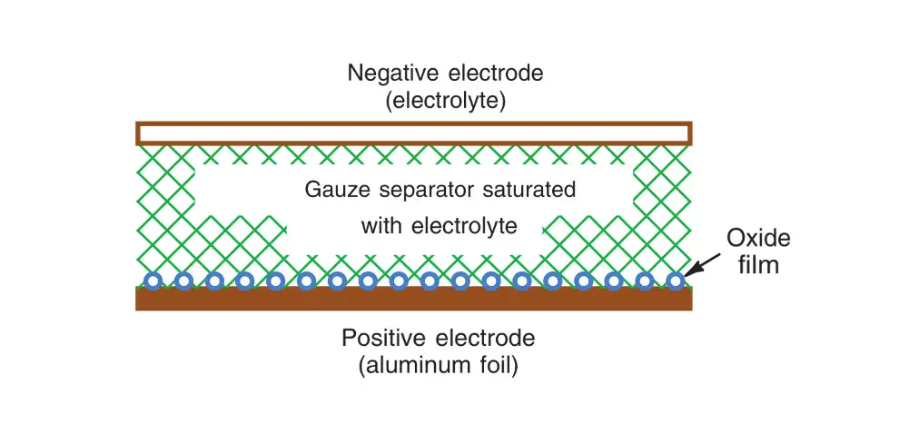
The two aluminium electrodes are in an electrolyte of borax, phosphate, or carbonate. Between the two aluminium strips, absorbent gauze soaks up the electrolyte to provide the required electrolysis that produces an oxide film. This type is considered a wet electrolytic, but it can be mounted in any position.

When dc voltage is applied to form the capacitance in the manufacture, the electrolytic action accumulates a molecular-thin layer of aluminium oxide at the junction between the positive aluminium foil and the electrolyte. The oxide film is an insulator. As a result, capacitance is formed between the positive aluminium electrode and the electrolyte in the gauze separator. The negative aluminium electrode simply provides a connection to the electrolyte. Usually, the metal can itself is the negative terminal of the capacitor, as shown in the figure.

Because of the extremely thin dielectric film, very large C values can be obtained. The area is increased by using long strips of aluminium foil and gauze, which are rolled into a compact cylinder with very high capacitance.

For example, an electrolytic capacitor the same size as a 0.1 μF paper capacitor, but rated at 10 V breakdown, may have 1000 μF of capacitance or more. Higher voltage ratings, up to 450 V, are available, with typical C values up to about 6800 μF. The very high C values usually have lower voltage ratings.

Electrolytic Capacitor Polarity

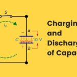
Electrolytic capacitors are used in circuits that have a combination of dc voltage and ac voltage.

The dc voltage maintains the required polarity across the electrolytic capacitor to form the oxide film.

A common application is for electrolytic filter capacitors to eliminate the 60- or 120-Hz ac ripple in a dc power supply. Another use is for audio coupling capacitors in transistor amplifiers.

In both applications, for filtering or coupling, electrolytes are needed for large C with a low-frequency ac component, whereas the circuit has a dc component for the required voltage polarity.

Incidentally, the difference between filtering out an ac component or coupling it into a circuit is only a question of parallel or series connections. The filter capacitors for a power supply are typically 100 to 1000 μF. Audio capacitors are usually 10 to 47μF.

If the electrolytic capacitor is connected in opposite polarity, the reversed electrolysis forms gas in the capacitor. It becomes hot and may explode. This is a possibility only with electrolytic capacitors.

Leakage Current

The disadvantage of electrolytes, in addition to the required polarization, is their relatively high leakage current compared with other capacitors, since the oxide film is not a perfect insulator.

The problem with leakage current in a capacitor is that it allows part of the dc component to be coupled into the next circuit along with the ac component. In newer electrolytic capacitors, the leakage current is quite small.

Section 16–10 takes a closer look at leakage current in capacitors.

Nonpolarized Electrolytic Capacitor

This type is available for applications in circuits without any dc polarizing voltage, as in a 60-Hz ac power line. One application is the starting capacitor for ac motors.

A nonpolarized electrolytic actually contains two capacitors, connected internally in series-opposing polarity.

Related Articles

  • Current 2BTransformer 2BConstruction 2Bor 2BCircuit 2BDiagram 2Band 2BSymbol
    Current Transformer (CT) - Construction and Working Principle

    A current transformer (CT) is a type of transformer that is used to measure AC…

  • Construction of High Voltage Current Transformer
    Basic Types of Current Transformers

    Current Transformers (CT’s) are instrument transformers that are used to supply a reduced value of…

  • capacitor charging and discharging
    Charging and Discharging a Capacitor

    Charging and discharging are the two main effects of capacitors. In this article, you will…

  • Types-of-Electric-current
    Types of Electric Current - Steady (DC), Varying & Alternating (AC) Current

    The directed flow of free electrons (or charge) is called the electric current. The electric…

  • universal motor construction
    Construction of Universal Motors

    A universal motor is one of the single-phase motors that can be operated on either…

  • cvt or ccvt
    Capacitor Voltage Transformer (CVT or CCVT) - Construction & Working

    Capacitor Voltage Transformer (CVT) or Capacitor Coupled Voltage Transformer (CCVT) is a switchgear device used…

  • Share:
Tesla Edison
Tesla Edison

Tesla is an Electrical Engineer, Physicist and an Inventor in making. He is a good writer and author of many courses and articles published in this site.

Previous post

What is an Electrical Fuse? Types, Properties, and Application
July 17, 2020

Next post

The efficient role of Brass Bushing
March 2, 2021

You may also like

Thin film application iin electronics
The Various Applications Of Thin Films In Electronics And Other Equipment
16 January, 2023
multimeter
Digital Multimeter: Working and Application
8 July, 2022
The PCB Assembly Procedure- Basic Information You Should Know
28 June, 2022

    1 Comment

  1. naman
    May 25, 2021
    Reply

    I just discovered a motivational thing while reading this , have any one observed that each and every thing is equally important to make run anything for a long that’s how we should work on ourself by giving equal importance to every factor .

Leave A Reply Cancel reply

Your email address will not be published. Required fields are marked *

Search Here

From Blog

What is an amplidyne
Amplidyne – Working and Application
15Sep2019
What is an amplidyne
Lightning Arrester – Location, Rating and Selection
23Jun2014
Construction of High Voltage Current Transformer
Basic Types of Current Transformers
26Oct2015
Transmission-switching
Why Do We Use Transmission Switching in Electricity Supplies?
08Aug2022

Categories

  • Alternator
  • Arduino
  • Basic Electrical
  • Battery
  • Books
  • Cables
  • Capacitor
  • Career
  • Circuit Breaker
  • Control System
  • DC Generator
  • DC Motor
  • Drives
  • Electric Vehicles
  • Electrical Circuits
  • Electrical Machines
  • Electrical Relays
  • Electrical Safety
  • Electronics
  • Embedded System
  • Exams
  • Generation
  • Guest Post
  • HVDC
  • Instrumentation
  • Interview Questions
  • Locomotives
  • Measurement
  • Microcontroller
  • Objective Questions
  • PCB
  • PLC
  • Power System
  • Problems and Solution
  • Projects
  • Resistor
  • Signals and Systems
  • Single Phase Motors
  • Substation
  • Switchgear
  • Synchronous Motor
  • Three Phase Induction Motor
  • Transformer
  • Transmission Line
  • Uncategorized

Copyright © 2021 Study Electrical, Inc.

© StudyElectrical.Com 2021

Login with your site account

Lost your password?

Not a member yet? Register now

Register a new account

Are you a member? Login now