• Home
  • Courses
  • Machines
    • Transformer
    • AC Motors
      • Induction Motor
      • Synchronous Motor
    • DC Motor
    • DC Generator
  • Power System
    • Circuit Breaker
    • Switchgear
    • Substation
    • Control System
    • Measurement
  • Electronics
  • Blog
  • Contact
    • Contact Us
    • Privacy Policy
Have any question?
[email protected]
RegisterLogin
StudyElectrical.Com
  • Home
  • Courses
  • Machines
    • Transformer
    • AC Motors
      • Induction Motor
      • Synchronous Motor
    • DC Motor
    • DC Generator
  • Power System
    • Circuit Breaker
    • Switchgear
    • Substation
    • Control System
    • Measurement
  • Electronics
  • Blog
  • Contact
    • Contact Us
    • Privacy Policy

Capacitor

Charging and Discharging a Capacitor

  • Categories Capacitor, Basic Electrical, Electrical Circuits, Electronics
capacitor charging and discharging

Charging and discharging are the two main effects of capacitors. In this article, you will learn about charging and discharging a capacitor.

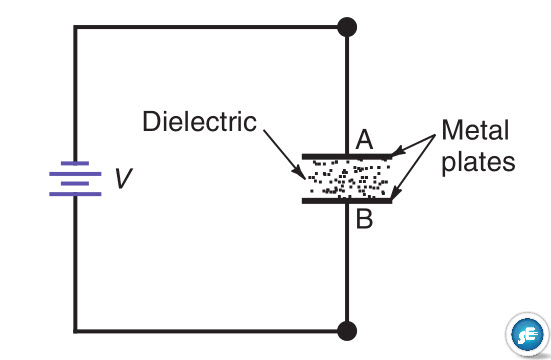
When a voltage is applied on a capacitor it puts a charge in the capacitor. This charge gets accumulated between the metal plates of the capacitor. The accumulation of charge results in a buildup of potential difference across the capacitor plates. So there is a voltage built across the capacitor.

how charge stored in a capacitor
The charge gets accumulated in the capacitor

When the capacitor voltage equals the applied voltage, there is no more charging. The charge remains in the capacitor, with or without the applied voltage connected.

The capacitor discharges when a conducting path is provided across the plates, without any applied voltage.

Actually, it is necessary only that the capacitor voltage be more than the applied voltage. Then the capacitor can serve as a voltage source, temporarily, to produce discharge current in the discharge path.

The capacitor discharge continues until the capacitor voltage drops to zero or is equal to the applied voltage.

Table of Contents

  • Applying the Charge
  • Storing the Charge
  • Discharging the Capacitor
    • Nature of the Capacitance
    • Related Articles

Applying the Charge

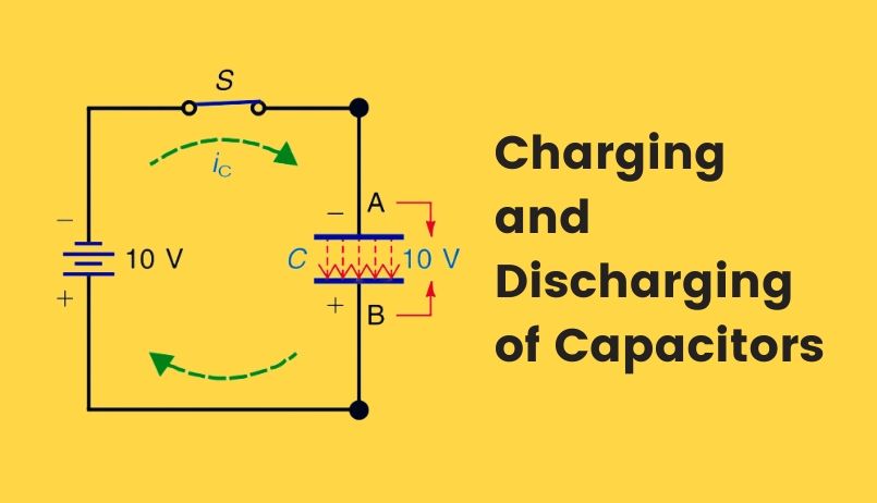
In the figure below, the capacitor is neutral with no charge because it has not been connected to any source of applied voltage and there is no electrostatic field in the dielectric.

Capacitor without any charge

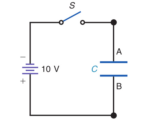
Closing the switch, however, allows the negative battery terminal to repel free electrons in the conductor to plate A.

Battery charges capacitor to applied voltage

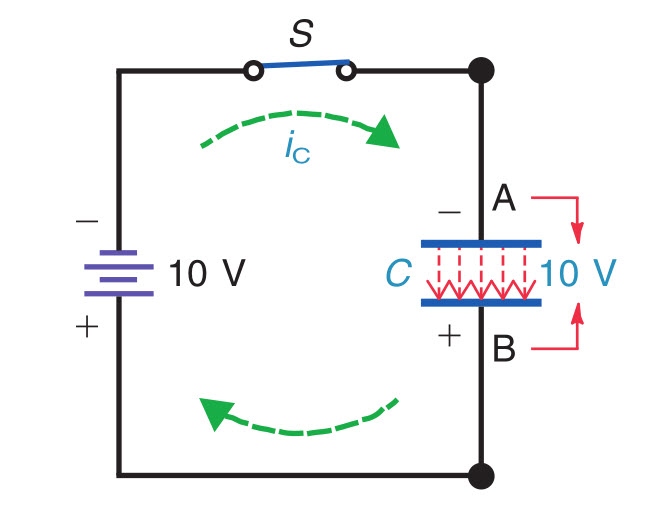
At the same time, the positive terminal attracts free electrons from plate B. The side of the dielectric at plate A accumulates electrons because they cannot flow through the insulator, and plate B has an equal surplus of protons.

Remember that opposite charges have an associated potential difference, which is the voltage across the capacitor. The charging process continues until the capacitor voltage equals the battery voltage, which is 10 V in this example.

Then no further charging is possible because the applied voltage cannot make free electrons flow in the conductors.

Note that the potential difference across the charged capacitor is 10 V between plates A and B. There is no potential difference from each plate to its battery terminal, however, which is why the capacitor stops charging.

Storing the Charge

The negative and positive charges on opposite plates have an associated electric field through the dielectric, as shown by the dotted lines.

Battery charges capacitor to applied voltage
Battery charges capacitor to the applied voltage
Stored charge remains in the capacitor,
The stored charge remains in the capacitor

The direction of these electric lines of force shown repelling electrons from plate B, making this side positive. The effect of electric lines of force through the dielectric results in storage of the charge.

The electric field distorts the molecular structure so that the dielectric is no longer neutral. The dielectric is actually stressed by the invisible force of the electric field. As evidence, the dielectric can be ruptured by a very intense field with a high voltage across the capacitor.

The result of the electric field, then, is that the dielectric has charge supplied by the voltage source. Since the dielectric is an insulator that cannot conduct, the charge remains in the capacitor even after the voltage source is removed, as illustrated.

Stored charge remains in the capacitor,

You can now take this charged capacitor by itself out of the circuit, and it still has 10 V across the two terminals.

Read how the charge is stored in a dielectric

Discharging the Capacitor

The action of neutralizing the charge by connecting a conducting path across the dielectric is called discharging the capacitor.

Discharging the capacitor

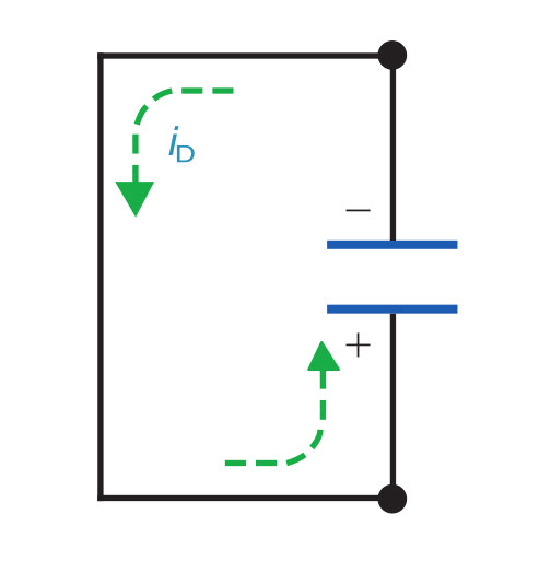
In the figure, the wire between plates A and B is a low-resistance path for discharge current. With the stored charge in the dielectric providing the potential difference, 10 V is available to produce discharge current.

The negative plate repels electrons, which are attracted to the positive plate through the wire until the positive and negative charges are neutralized. Then there is no net charge.

The capacitor is completely discharged, the voltage across it equals zero, and there is no discharge current.

Now the capacitor is in the same uncharged condition.

Capacitor without any charge

It can be charged again, however, by a source of the applied voltage.

Nature of the Capacitance

A capacitor can store the amount of charge necessary to provide a potential difference equal to the charging voltage. If 100 V were applied, the capacitor would charge to 100 V.

The capacitor charges to the applied voltage because it takes on more charge when the capacitor voltage is less. As soon as the capacitor voltage equals the applied voltage, no more charging current can flow.

Note that any charge or discharge current flows through the conducting wires to the plates but not through the dielectric.


Related Articles

  • Collection of different types of capacitors
    Different Types of Capacitors and their Uses

    Basically, a capacitor is formed from two conducting plates separated by a thin insulating layer. There…

  • cvt or ccvt
    Capacitor Voltage Transformer (CVT or CCVT) - Construction & Working

    Capacitor Voltage Transformer (CVT) or Capacitor Coupled Voltage Transformer (CCVT) is a switchgear device used…

  • Capacitor-start-induction-run
    Split Phase and Capacitor Start Induction Motors

    Before reading Split Phase and Capacitor Start Induction Motors, please read the previous article, Why…

  • Capacitor-start-induction-run
    Capacitor Start Single Phase Induction Motor - Working and Characteristics

    The capacitor start single phase induction motor is a type of split-phase induction motor. Capacitors…

  • electrolytic capacitors
    Electrolytic Capacitor - Types, Construction, Polarity and Leakage Current

    Electrolytic capacitors are one of the most commonly used types of capacitor. Their capacitance values…

  • Air Variable Capacitor
    How Charge is Stored in a Dielectric?

    Did you wonder how charge get stored in a dielectric material. Is it really possible?…

  • Share:
Tesla Edison
Tesla Edison

Tesla is an Electrical Engineer, Physicist and an Inventor in making. He is a good writer and author of many courses and articles published in this site.

Previous post

How Charge is Stored in a Dielectric?
February 29, 2020

Next post

Beginner Friendly Kits That Most Newbie Used In Electronics
March 16, 2020

You may also like

Thin film application iin electronics
The Various Applications Of Thin Films In Electronics And Other Equipment
16 January, 2023
Thin film resistors
Applications & Functions of Thin Film Resistors
12 January, 2023
Residential Electrical Wiring - 3 Surprising Dangers
Maintaining Residential Electrical Wiring – 3 Surprising Dangers to Look out For
6 September, 2022

    2 Comments

Leave A Reply Cancel reply

Your email address will not be published. Required fields are marked *

Search Here

From Blog

5 Types of DC Motors | Series, Shunt, and Compound
27Dec2014
assignment
Basic Tips for Students to Write an Essay
13Sep2021
Double end break disconnect switch
Disconnect Switches (Isolator) in Substation: Types, Design and Working
01Sep2022
Electrodynamometer or Electrodynamic instrument
Electrodynamometer Instruments – Ammeter, Voltmeter and Wattmeter
25Nov2019

Categories

  • Alternator
  • Arduino
  • Basic Electrical
  • Battery
  • Books
  • Cables
  • Capacitor
  • Career
  • Circuit Breaker
  • Control System
  • DC Generator
  • DC Motor
  • Drives
  • Electric Vehicles
  • Electrical Circuits
  • Electrical Machines
  • Electrical Relays
  • Electrical Safety
  • Electronics
  • Embedded System
  • Exams
  • Generation
  • Guest Post
  • HVDC
  • Instrumentation
  • Interview Questions
  • Locomotives
  • Measurement
  • Microcontroller
  • Objective Questions
  • PCB
  • PLC
  • Power System
  • Problems and Solution
  • Projects
  • Resistor
  • Signals and Systems
  • Single Phase Motors
  • Substation
  • Switchgear
  • Synchronous Motor
  • Three Phase Induction Motor
  • Transformer
  • Transmission Line
  • Uncategorized

Copyright © 2021 Study Electrical, Inc.

© StudyElectrical.Com 2021

Login with your site account

Lost your password?

Not a member yet? Register now

Register a new account

Are you a member? Login now