• Home
  • Courses
  • Machines
    • Transformer
    • AC Motors
      • Induction Motor
      • Synchronous Motor
    • DC Motor
    • DC Generator
  • Power System
    • Circuit Breaker
    • Switchgear
    • Substation
    • Control System
    • Measurement
  • Electronics
  • Blog
  • Contact
    • Contact Us
    • Privacy Policy
Have any question?
[email protected]
RegisterLogin
StudyElectrical.Com
  • Home
  • Courses
  • Machines
    • Transformer
    • AC Motors
      • Induction Motor
      • Synchronous Motor
    • DC Motor
    • DC Generator
  • Power System
    • Circuit Breaker
    • Switchgear
    • Substation
    • Control System
    • Measurement
  • Electronics
  • Blog
  • Contact
    • Contact Us
    • Privacy Policy

Electrical Machines

Split Phase and Capacitor Start Induction Motors

  • Categories Electrical Machines, Single Phase Motors
Capacitor-start-induction-run

Before reading Split Phase and Capacitor Start Induction Motors, please read the previous article, Why a Single Phase Induction Motor is not Self Starting?

Table of Contents

    • Making a Single Phase Induction Motor Self Starting
  • Crating Phase difference between two windings
    • Split Phase Induction Motor
    • Capacitor Start Induction run motors
    • Related Articles

Making a Single Phase Induction Motor Self Starting

As discussed in the previous article single-phase induction motors are not self-starting. It is because a single-phase supply cannot produce a rotating magnetic field. But we can create a rotating magnetic field by a two-phase construction.

So simply we can say in order to make a single-phase induction motor self-starting, we have to temporarily convert it into a two-phase motor during its starting period.
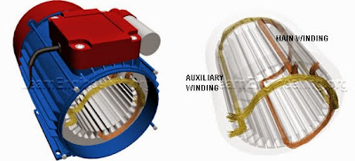
Auxiliary Winding and Main Winding

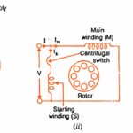
For this purpose, the stator of the single-phase induction motor is provided with an extra winding known as Starting or Auxillary Winding in addition to the Main or Running Winding. The two winding are 90 degrees electrically displaced and are connected in parallel across the single-phase supply.
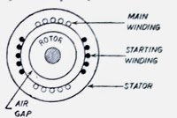
Main Winding and Starting Winding
Main Winding and Starting Winding of a Single Phase Induction Motor
It is so arranged that the phase difference between the currents in two stator windings ( main and running windings ) is very large ( ideal value is 90 degrees). Hence the motor behaves like a two-phase motor. These two currents produce a revolving flux and hence make the motor self-starting.

The phase difference between the currents in the main winding and running winding can be obtained through different methods. The phase shift can be achieved by connecting a resistance, inductance or capacitance in series with the starting winding. 

Crating Phase difference between two windings

Split Phase Induction Motor

In a split-phase machine, the main-winding has low resistance but high reactance whereas the starting winding has a high resistance but low reactance.

Split Phase Motor and Phasor Diagram

The resistance of the starting winding may be increased either by connecting a high resistance R in series with it or by choosing a high-resistance fine copper wire for winding purposes. 

Hence, as shown in Fig (b), the current Is drawn by the starting winding lags behind the applied voltage by a small angle whereas current Im taken by the main winding lags behind V by a very large angle. The phase angle between Is and Im is made as large as possible because the starting torque of a split-phase motor is proportional to sin α.

A centrifugal switch S is connected in series with the starting winding and is located inside the motor. Its function is to automatically disconnect the starting winding from the supply when the motor has reached 70 to 80 percent of its full load speed. 

The centrifugal switch is necessary because the auxiliary winding cannot support high currents for more than a few seconds without being damaged because it is made of fine wire. In case of a capacitor start motor its is necessary because most motors use a cheap electrolytic capacitor that can only carry a.c current for a short period of time.

In the case of split-phase motors that are hermetically sealed in refrigeration units, instead of an internally mounted centrifugal switch, an electromagnetic type of relay is used.

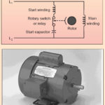
As shown in figure, the relay coil is connected in series with main winding and the pair of contacts which are normally open, is included in the starting winding. During the starting period when Im is large, relay contacts close thereby allowing Is to flow and the motor starts as usual. After motor speeds up to 75 percent of full-load speed, Im drops to value that is low enough to cause the contacts to open.

These motors are often used in preference to the costlier capacitor-start motors.

Typical applications of split-phase motors are fans and blowers, centrifugal pumps and separators, washing machines, small machine tools, duplicating machines, domestic refrigerators, and oil burners, etc. Commonly available sizes range from 1/20 to 1/3 h.p. (40 to 250 W) with speeds ranging from 3,450 to 865 r.p.m.

The direction of rotation of such motors can be reversed by reversing the connections of one of the two stator windings (riot both). For this purpose, the four leads are brought outside the frame. As seen from the figure, the connections of the starting winding have been reversed.

The speed regulation of standard split-phase motors is nearly the same as of the 3-phase motors. Their speed varies about 2 to 5% between no load and full- load’ For this reason such motors are usually regarded as practically constant-speed motors.

Read: Shaded Pole Induction Motor

Capacitor Start Induction run motors

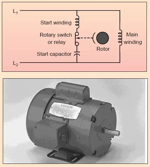
In these motors, the necessary phase difference between Is and Im is produced by connecting a capacitor in series with the starting winding as shown in Fig. The capacitor is generally of the electrolytic type and is usually mounted on the outside of the motor as a separate unit.

The capacitor is designed for extremely short-duty service and is guaranteed for not more than 20 periods of operation per hour, each period not to exceed 3 seconds. When the motor reaches about 75 percent of fulls speed, the centrifugal switch S opens and cuts out both the starting winding and the capacitor from the supply, thus leaving only the running winding across the lines.
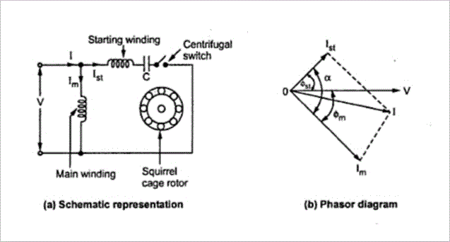
Capacitor-start Induction run motors

As shown in Fig, current Im drawn by the main winding lags the supply voltage V by a large angle whereas Is leads V by a certain angle. The two currents are out of phase with each other by about 80° (for a 200-W 50-Hz motor) as compared to nearly 30 degrees for a split phase motor. Their resultant current I is small and is almost in phase with V as shown in figure. 
Since the torque developed by a split-phase motor is proportional to the sine of the angle between Is and Im, it is obvious that the increase in the angle ( from 30 to 80 ) alone increases the starting torque to nearly twice the value developed by a standard split-phase induction motor. Other improvements in motor design have made it possible to increase the starting torque to a value as high as 350 to 450 percent.

Related Articles

  • Capacitor-start-induction-run
    Capacitor Start Single Phase Induction Motor - Working and Characteristics

    The capacitor start single phase induction motor is a type of split-phase induction motor. Capacitors…

  • single phase ac motors
    AC Single Phase Motors

    Single phase motors are the most familiar of all electric motors because they are extensively…

  • Construction of Three Phase Induction Motor
    Three Phase Induction Motors - Construction

    A three phase induction motor has two main parts stator  rotor. The rotor is separated…

  • Split Phase Induction Motor
    Split Phase Induction Motor - Operation and Characteristics

    Before going to the operation and characteristics of split-phase induction motor we should first understand…

  • video how single phase motor works
    Video - How Single Phase Induction Motor Works?

    Read about working of induction motors here. All topics under single phase induction motor are…

  • universal motor construction
    Construction of Universal Motors

    A universal motor is one of the single-phase motors that can be operated on either…

  • Share:
author avatar

Previous post

Power Transformer and Distribution Transformer

Next post

Losses in DC Machine ( DC Generator and Motor )

You may also like

methods of magnetizing steel bar
3 Methods of Magnetizing a Steel Bar
Electromagnetics Lecture Notes PDF
[PDF] Electromagnetism Lecture Notes – University of Cambridge
Electrical Engineering Basics - The ultimate guide
Electrical Engineering Basics: The Ultimate Guide

    2 Comments

  1. mayhap
    August 9, 2019
    Reply

    Well explained. Now I understood working of Split Phase and Capacitor Start Induction Motors

Leave A Reply Cancel reply

Your email address will not be published. Required fields are marked *

Search Here

From Blog

DC Shunt Generator Characteristics
Characteristics of DC Shunt Generator
Programmable%2Blogic%2Bcontroller%2BPLC%2BLectures%2BNotes
14 Lectures on Programmable Logic Controllers (PLC)
Energy band diagram of conductor semiconductor insulator
Insulators, Conductors and Semiconductors (with Band Diagram)
electrical safety rules
Electric Safety: 5 Rules You Need to Know

Categories

  • Alternator
  • Arduino
  • Basic Electrical
  • Battery
  • Books
  • Cables
  • Capacitor
  • Career
  • Circuit Breaker
  • Control System
  • DC Generator
  • DC Motor
  • Electric Vehicles
  • Electrical Circuits
  • Electrical Machines
  • Electrical Relays
  • Electrical Safety
  • Electronics
  • Embedded System
  • Exams
  • Generation
  • Guest Post
  • HVDC
  • Instrumentation
  • Interview Questions
  • Locomotives
  • Measurement
  • Microcontroller
  • Objective Questions
  • PCB
  • PLC
  • Power System
  • Projects
  • Signals and Systems
  • Single Phase Motors
  • Substation
  • Switchgear
  • Synchronous Motor
  • Three Phase Induction Motor
  • Transformer
  • Transmission Line
  • Uncategorized

Copyright © 2021 Study Electrical, Inc.

© StudyElectrical.Com 2021

Login with your site account

Lost your password?

Not a member yet? Register now

Register a new account

Are you a member? Login now