• Home
  • Courses
  • Machines
    • Transformer
    • AC Motors
      • Induction Motor
      • Synchronous Motor
    • DC Motor
    • DC Generator
  • Power System
    • Circuit Breaker
    • Switchgear
    • Substation
    • Control System
    • Measurement
  • Electronics
  • Blog
  • Contact
    • Contact Us
    • Privacy Policy
Have any question?
[email protected]
RegisterLogin
StudyElectrical.Com
  • Home
  • Courses
  • Machines
    • Transformer
    • AC Motors
      • Induction Motor
      • Synchronous Motor
    • DC Motor
    • DC Generator
  • Power System
    • Circuit Breaker
    • Switchgear
    • Substation
    • Control System
    • Measurement
  • Electronics
  • Blog
  • Contact
    • Contact Us
    • Privacy Policy

Capacitor

How Charge is Stored in a Dielectric?

  • Categories Capacitor, Basic Electrical, Battery, Electronics
Air Variable Capacitor

Did you wonder how charge get stored in a dielectric material. Is it really possible?

Yes, it is possible for dielectric materials such as air or paper to hold an electric charge. This is because free electrons cannot flow through an insulator. However, the charge must be applied by some source.

I know you didn’t understand the above statement.

Don’t worry.

By the end of this article, you will clearly understand how electric charge is stored in a dielectric.

Dielectric inside capacitor
Dielectric placed between foil

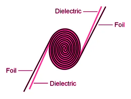
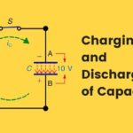
In the figure below the battery can charge the capacitor shown. The capacitor have two metal plates A and B. The dielectric is placed between the metal plates or foil. Now I will explain this basic electrical engineering concept on how the charge from the battery is stored in the dielectric of capacitor.

Dielectric inside capacitor
Battery charging a capacitor

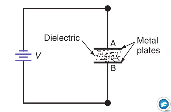
With the dielectric contacting the two conductors connected to the potential difference V , electrons from the voltage source accumulate on the side of the capacitor connected to the negative terminal of V . The opposite side of the capacitor connected to the positive terminal of V loses electrons.

As a result, the excess of electrons produces a negative charge on one side of the capacitor, and the opposite side has a positive charge.

As an example, if 6.25 * 1018 electrons are accumulated, the negative charge equals 1 coulomb (C).
The charge on only one plate need be considered because the number of electrons accumulated on one plate is exactly the same as the number taken from the opposite plate.

What the voltage source does is simply redistribute some electrons from one side of the capacitor to the other. This process is called charging the capacitor.

Charging continues until the potential difference across the capacitor is equal to the applied voltage. Without any series resistance, the charging is instantaneous. Practically, however, there is always some series resistance.

This charging current is transient, or temporary; it flows only until the capacitor is charged to the applied voltage. Then there is no current in the circuit.

The result is a device for storing charge in the dielectric. Storage means that the charge remains even after the voltage source is disconnected. The measure of how much charge can be stored is the capacitance C .

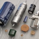
More charge stored for a given amount of applied voltage means more capacitance. Components made to provide a specified amount of capacitance are called capacitors, or by their old name condensers.

In the automotive industry capacitors are commonly referred to as condensers. In the electronics industry, however, capacitors are rarely, if ever, referred to as condensers.

Electrically, then, capacitance is the ability to store charge. A capacitor consists simply of two conductors separated by an insulator.

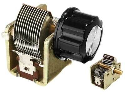
For example, figure below shows a variable capacitor using air for the dielectric between the metal plates.

Air Variable Capacitor

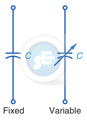
There are many types of capacitors with different dielectric materials, including paper, mica, and ceramics, but the schematic symbols shown apply to all capacitors.

Fixed and Variable Capacitor symbol

Read more about different types of capacitors and their uses.

Electric Field in the Dielectric

Any voltage has a field of electric lines of force between the opposite electric charges. The electric field corresponds to the magnetic lines of force of the magnetic field associated with electric current.

What a capacitor does is concentrate the electric field in the dielectric between the plates. This concentration corresponds to a magnetic field concentrated in the turns of a coil.

The only function of the capacitor plates and wire conductors is to connect the voltage source V across the dielectric. Then the electric field is concentrated in the capacitor, instead of being spread out in all directions.

Electrostatic Induction

The capacitor has opposite charges because of electrostatic induction by the electric field.

Electrons that accumulate on the negative side of the capacitor provide electric lines of force that repel electrons from the opposite side.

When this side loses electrons, it becomes positively charged. The opposite charges induced by an electric field correspond to the opposite poles induced in magnetic materials by a magnetic field.

Related Articles

  • Capacitor-start-induction-run
    Split Phase and Capacitor Start Induction Motors

    Before reading Split Phase and Capacitor Start Induction Motors, please read the previous article, Why…

  • Capacitor-start-induction-run
    Capacitor Start Single Phase Induction Motor - Working and Characteristics

    The capacitor start single phase induction motor is a type of split-phase induction motor. Capacitors…

  • electrolytic capacitors
    Electrolytic Capacitor - Types, Construction, Polarity and Leakage Current

    Electrolytic capacitors are one of the most commonly used types of capacitor. Their capacitance values…

  • capacitor charging and discharging
    Charging and Discharging a Capacitor

    Charging and discharging are the two main effects of capacitors. In this article, you will…

  • Collection of different types of capacitors
    Different Types of Capacitors and their Uses

    Basically, a capacitor is formed from two conducting plates separated by a thin insulating layer. There…

  • insulation resistance measurement vs dielectric breakdown testing
    Difference between Dielectric Testing & Insulation Resistance Measurement

    All electrical installations and equipment comply with insulation resistance specifications so they can operate safely.  Whether…

  • Share:
Tesla Edison

Tesla is an Electrical Engineer, Physicist and an Inventor in making. He is a good writer and author of many courses and articles published in this site.

Previous post

Teach Yourself Electricity and Electronics

Next post

Charging and Discharging a Capacitor

You may also like

Electric current concept
Concept of Electric Charge and Current
dc voltage source
What is a Voltage Source? | DC and AC Voltage Sources Explained
electrolytic capacitors
Electrolytic Capacitor – Types, Construction, Polarity and Leakage Current

    2 Comments

Leave A Reply Cancel reply

Your email address will not be published. Required fields are marked *

Search Here

From Blog

condition-monitoring-transformer
Condition Monitoring for Transformers
Shackle-Insulator-Spool-Insulator
Shackle insulator (Spool Insulator)
moulded case circuit breaker
Moulded Case Circuit Breaker (MCCB) – Types and Working
Substation-components-equipment-layout
Electrical Substation: Equipment, Types, Components & Functions

Categories

  • Alternator
  • Arduino
  • Basic Electrical
  • Battery
  • Books
  • Cables
  • Capacitor
  • Career
  • Circuit Breaker
  • Control System
  • DC Generator
  • DC Motor
  • Electric Vehicles
  • Electrical Circuits
  • Electrical Machines
  • Electrical Relays
  • Electrical Safety
  • Electronics
  • Embedded System
  • Exams
  • Generation
  • Guest Post
  • HVDC
  • Instrumentation
  • Interview Questions
  • Locomotives
  • Measurement
  • Microcontroller
  • Objective Questions
  • PCB
  • PLC
  • Power System
  • Projects
  • Signals and Systems
  • Single Phase Motors
  • Substation
  • Switchgear
  • Synchronous Motor
  • Three Phase Induction Motor
  • Transformer
  • Transmission Line
  • Uncategorized

Copyright © 2021 Study Electrical, Inc.

© StudyElectrical.Com 2021

Login with your site account

Lost your password?

Not a member yet? Register now

Register a new account

Are you a member? Login now