A DC motor can be made using different types of armatures based on its application. There are 2 types of armatures.
- Gramme Ring Armature
- Drum Wound Armature
Gramme Ring Armature
The Gramme-ring armature is constructed by winding an insulated wire around a soft-iron ring.
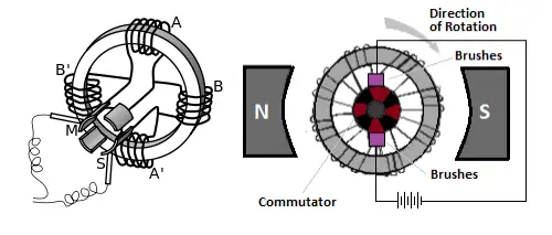
Eight equally spaced connections are made to the winding. Each of these is connected to a commutator segment. The brushes touch only the top and bottom segments. There are two parallel paths for current to follow — one up the left side and one-up the right side.
These paths are completed through the top brush back to the positive lead of the battery.
To check the direction of rotation of this armature, you should use the right-hand rule for motors.
Hold your thumb, forefinger, and middle finger at right angles. Point your forefinger in the direction of field flux; in this case, from left to right. Now turn your wrist so that your middle finger points in the direction that the current flows in the winding on the outside of the ring. Note that current flows into the page (away from you) in the left-hand windings and out of the page (toward you) in the right-hand windings. Your thumb now points in the direction that the winding will move.
The Gramme-ring armature is seldom used in modern DC motors. The windings on the inside of the ring are shielded from the magnetic flux, which causes this type of armature to be inefficient.
The Gramme-ring armature is discussed primarily to help you better understand the drum-wound armature.
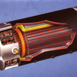
Drum Wound Armature
The drum-wound armature is generally used in AC motors. It is identical to the drum winding discussed in the chapter on DC generators.
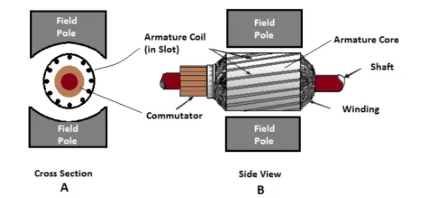
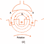
If the drum-wound armature were cut in half, an end view at the cut would resemble the drawing in the figure (view A), (view B) is a side view of the armature and pole pieces.
Notice that the length of each conductor is positioned parallel to the faces of the pole pieces. Therefore, each conductor of the armature can cut the maximum flux of the motor field. The inefficiency of the Gramme-ring armature is overcome by this positioning.
The direction of current flow is marked in each conductor in the figure (view A) as though the armature were turning in a magnetic field. The dots show that current is flowing toward you on the left side, and the crosses show that the current is flowing away from you on the right side.
Strips of insulation are inserted in the slots to keep windings in place when the armature spins. These are shown as wedges in the figure (view A).