• Home
  • Courses
  • Machines
    • Transformer
    • AC Motors
      • Induction Motor
      • Synchronous Motor
    • DC Motor
    • DC Generator
  • Power System
    • Circuit Breaker
    • Switchgear
    • Substation
    • Control System
    • Measurement
  • Electronics
  • Blog
  • Contact
    • Contact Us
    • Privacy Policy
Have any question?
[email protected]
RegisterLogin
StudyElectrical.Com
  • Home
  • Courses
  • Machines
    • Transformer
    • AC Motors
      • Induction Motor
      • Synchronous Motor
    • DC Motor
    • DC Generator
  • Power System
    • Circuit Breaker
    • Switchgear
    • Substation
    • Control System
    • Measurement
  • Electronics
  • Blog
  • Contact
    • Contact Us
    • Privacy Policy

DC Generator

Characteristics of Series Wound DC Generators

  • Categories DC Generator, Electrical Machines
Dc series generator characteristics

In this post, you will learn the characteristics of a series wound dc generator. This article is the continuation of the dc generator characteristics.

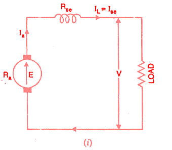
The connection diagram of a series-wound generator is shown in the figure below. 

dc series generator connection
Dc series generator connection
Since there is only one current (that which flows through the whole machine), the load current is the same as the exciting current.

The open circuit, internal and external characteristics of series wound dc generators are discussed here.

Table of Contents

  • Open circuit characteristic
  • Internal characteristic
  • External or Load characteristic
  • Related Articles

Open circuit characteristic

Curve 1 shows the open circuit characteristic (O.C.C.) of a series generator. Curve 2 shows the total or internal characteristics of a series generator. Curve 3 shows the external characteristic of a series generator.

It can be obtained experimentally by disconnecting the field winding from the machine and exciting it from a separate DC source as discussed in dc generator characteristics.
Dc series generator characteristics

Internal characteristic

Curve 2 shows the total or internal characteristics of a series generator. It gives the relation between the generated e.m.f. E. on load and armature current.

internal characteristics
Internal characteristics

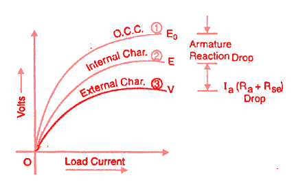
Due to the armature reaction in the dc generator, the flux in the machine will be less than the flux at no load.

Hence, e.m.f. E generated under load conditions will be less than the e.m.f. E0 generated under no-load conditions.

Consequently, the internal characteristic curve lies below the OCC curve; the difference between them representing the effect of armature reaction.

This curve also gives the relation between emf Eg and armature current Ia since Ia=If. 

External or Load characteristic

Curve 3 shows the external characteristic of a series generator.

It gives the relation between terminal voltage and load current IL.

V = E – Ia (Ra + Rse )

Therefore, external characteristic curve will lie below internal characteristic curve by an amount equal to ohmic drop [i.e., Ia(Ra + Rse)] in the machine.

preview file+(1)
External vs Internal Characteristics
This voltage drop for different values of load current may be represented by straight-line OC. 
 
The internal and external characteristics of a dc series generator can be plotted from one another as shown in the figure above.
Suppose we are given the internal characteristic of the generator. Let the line OC represent the resistance of the whole machine i.e. Ra + Rse.
If the load current is OB, drop in the machine is AB i.e. AB = Ohmic drop in the machine = OB(Ra + Rse)
 
Now raise a perpendicular from point B and mark a point b on this line such that ab = AB. Then point b will lie on the external characteristic of the generator.
Following a similar procedure, other points of the external characteristic can be located.
It is easy to see that we can also plot internal characteristics from the external characteristic. So external characteristic is what we obtain by deducting ohmic drop from internal characteristics. 

Note:
From the external characteristic, it is observed that the terminal voltage first increases with the increase in load, reaches the maximum and finally decreases.
If the load resistance is reduced sufficiently, the terminal voltage may fall to zero. So if the series generator is operated on the initial straight-line portion of the characteristic, it gives voltage approximately proportional to the load current.

If it is operated on the drooping portion of the characteristic, it gives approximately constant current irrespective of the external load circuit resistance.


Related Articles

  • external-characteristics-of-dc-compound-generator.
    Characteristics of DC Compound Generator

    In a compound generator, both series and shunt excitation are combined as shown in the…

  • external-characteristic-of-seperately-excited-dc-generator
    Characteristics of Separately Excited DC Generators

    In a separately excited dc generator, the field coils are energized from an independent source. …

  • parallel operation of series dc generator
    Parallel Operation of DC Series Generator

    The interesting thing about the parallel operation of the DC series generator is that DC…

  • DC Shunt Generator Characteristics
    Characteristics of DC Shunt Generator

    In this article, you will learn the characteristics of a dc shunt generator. A shunt…

  • dc motor characteristics
    Characteristics of DC Series Motor

    In this post, we will look into the characteristics of a DC series motor. A…

  • dc generator open circuit characteristics
    DC Generator Characteristics

    DC generator characteristics are the relations between excitation, terminal voltage and load exhibited graphically by…

  • Share:
author avatar

Previous post

Characteristics of Separately Excited DC Generators

Next post

Characteristics of DC Shunt Generator

You may also like

methods of magnetizing steel bar
3 Methods of Magnetizing a Steel Bar
Electromagnetics Lecture Notes PDF
[PDF] Electromagnetism Lecture Notes – University of Cambridge
Electrical Engineering Basics - The ultimate guide
Electrical Engineering Basics: The Ultimate Guide

    1 Comment

Leave A Reply Cancel reply

Your email address will not be published. Required fields are marked *

Search Here

PCBWay

From Blog

Auto Reclosing principle
Auto Reclosing of Power Lines and Types of Faults
Moving coil instrument construction
Permanent Magnet Moving Coil (PMMC) Instrument
Moving Iron Instruments Banner
Moving Iron Instruments – Attraction and Repulsion Type
Three Phase Transformer
Three-Phase Transformer – Basics and Connection Methods

Categories

  • Alternator
  • Arduino
  • Basic Electrical
  • Battery
  • Books
  • Cables
  • Capacitor
  • Career
  • Circuit Breaker
  • Control System
  • DC Generator
  • DC Motor
  • Electric Vehicles
  • Electrical Circuits
  • Electrical Machines
  • Electrical Relays
  • Electrical Safety
  • Electronics
  • Embedded System
  • Exams
  • Generation
  • Guest Post
  • HVDC
  • Instrumentation
  • Interview Questions
  • Locomotives
  • Measurement
  • Microcontroller
  • Objective Questions
  • PCB
  • PLC
  • Power System
  • Projects
  • Signals and Systems
  • Single Phase Motors
  • Substation
  • Switchgear
  • Synchronous Motor
  • Three Phase Induction Motor
  • Transformer
  • Transmission Line
  • Uncategorized

Copyright © 2021 Study Electrical, Inc.

© StudyElectrical.Com 2021

Login with your site account

Lost your password?

Not a member yet? Register now

Register a new account

Are you a member? Login now