Compensating Windings and Interpoles are one of the important step taken to minimize the undesirable effect of armature reaction in dc machines.
Armature reaction causes many undesirable effects on a DC machine such as sparking on brushes. So, necessary steps should be taken to minimize the effects of armature reaction.
How to Minimise Effect of Armature Reaction?
One easy and simplest way is to shift the brushes to the new position of the magnetic neutral plane. Shifting the brushes to the advanced position (the new neutral plane) does not completely solve the problems of armature reaction.
The effect of armature reaction varies with the load current. Therefore, each time the load current varies, the neutral plane shifts. This means the brush position must be changed each time the load current varies.
Where Compensating windings and Interpoles are Used?
In small generators, the effects of armature reaction are reduced by actually mechanically shifting the position of the brushes.
The practice of shifting the brush position for each current variation is not practiced except in small generators. In larger generators, other means are taken to eliminate armature reaction. Compensating Windings or Interpoles are used for this purpose.
Compensating Windings
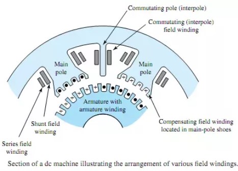
The compensating windings consist of a series of coils embedded in slots in the pole faces. These coils are connected in series with the armature.
The series-connected compensating windings produce a magnetic field, which varies directly with armature current. Because the compensating windings are wound to produce a field that opposes the magnetic field of the armature, they tend to cancel the cross magnetizing effect of the armature magnetic field.
The neutral plane will remain stationary and in its original position for all values of armature current. Because of this, once the brushes have been set correctly, they do not have to be moved again.
To neutralize completely the effects of armature reaction, a second set of auxiliary field windings, known as the compensating windings, is used in high-power d.c. machines.
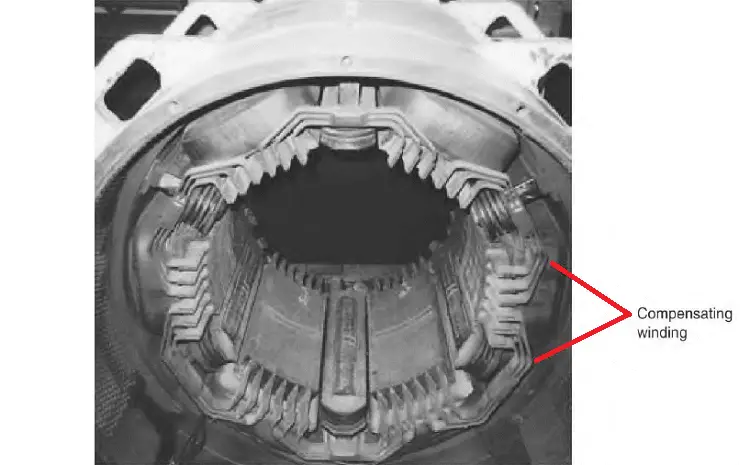
Compensation windings consist of a few turns of low-resistance copper bar laid in slots in the faces of the main shunt field pole pieces and so connected that the windings carry current in the reverse direction to that of the immediately adjacent armature conductors.
The compensating windings are connected in series with each other and with the armature winding in a manner similar to the interpole windings so that they also oppose the field set up by armature reaction. The current in them is then equal to that in the armature.
The field resulting from the compensating windings is wide in comparison with the commutating fields but weaker since the flux is less concentrated.
The effect of the two windings acting in conjunction is to neutralize completely the effects of armature reaction in respect to the shifting of the neutral plane and to eliminate almost completely the distorting effects.
Thus it is ensured that the neutral plane will remain in a fixed position throughout the entire range of load and speed of the machine, and, in the ease of a motor, in both directions of rotation.
Good commutation is thus affected with the brushes located in a fixed position.
Read: Construction of DC Machines
Interpole (Commutator Field Winding)
Another way to reduce the effects of armature reaction is to place small auxiliary poles called “interpoles” between the main field poles. The interpoles have a few turns of large wire and are connected in series with the armature.
The commutating field, or interpoles, as they are sometimes called because of their position relative to the main poles, consist of a series of small poles similar to the main field poles in construction and method of fastening, but having a winding that consists of a few turns of heavy copper bus bar of high current capacity and low resistance.

Interpoles are wound and placed so that each interpole has the same magnetic polarity as the main pole ahead of it, in the direction of rotation. The field generated by the interpoles produces the same effect as the compensating winding.
This field, in effect, cancels the armature reaction for all values of load current by causing a shift in the neutral plane opposite to the shift caused by armature reaction. The amount of shift caused by the interpoles will equal the shift caused by armature reaction since both shifts are a result of armature current.
The commutating pole (Interpole) windings are all connected in series with each other and with the armature circuit. A resistor connected in parallel with the commutating pole (Interpole) windings is adjusted and permanently set at the factory to give the commutating pole strength that results in the best commutation.
Most of the armature current goes through the commutating pole windings; only a small amount goes through the shunting resistor.
Since the armature reaction increases when the armature load current increases, and the effect of the commutating poles (Interpoles) also increases, the result is that the neutral or commutating plane is maintained in a fixed position throughout the load range.
With this method of correction, some distortion of the field still remains because the commutating fields, being small, are not completely effective in correcting the distortion in the vicinity of the main pole tips. This latter condition is especially true of the high-power, compact machines used for submarine propulsion.