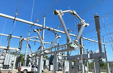
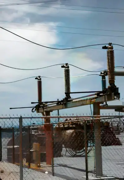
Disconnect switches are mechanical devices that play a vital role in high-voltage systems by providing an open point in an electrical circuit. They are primarily used for the isolation of various substation equipment, including circuit breakers, power transformers, capacitor banks, and reactors. Disconnect switches are also known as isolators in some part of the world.
Key Functions of Disconnect Switches
The three most important functions disconnect switches must perform are
- to open and close reliably when called to operate,
- to carry load currents continuously without overheating,
- and to remain in the closed operation position under fault current conditions.
They are normally used to provide a point of visual isolation of the substation equipment for maintenance.
Typically a disconnect switch would be installed on each side of a piece of substation equipment to provide a visible confirmation that the power conductors have been opened for personnel safety.
Visual Isolation for Maintenance
One of the primary purposes of disconnect switches is to provide a point of visual isolation for substation equipment during maintenance activities. This visual isolation is crucial for personnel safety.
A disconnect switch is installed on each side of the equipment to confirm that power conductors have been safely opened. This allows workers to attach portable safety grounds to de-energized equipment for added protection.
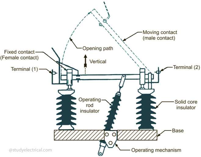
Design of Disconnect Switch
Disconnect switches are designed to carry load currents continuously and short circuit currents momentarily for a specified duration (usually measured in seconds or cycles according to the magnitude of the short-circuit current).
The switch is designed for no-load switching, opening or closing circuits where negligible currents are made or interrupted (including capacitive current and resistive or inductive current) or when there is no significant voltage across the open switch terminals.
They are relatively slow-speed operating devices. As a result, they are not designed to interrupt any significant magnitude current arcs. There are also switches that can be installed for bypassing breaker or other equipment for maintenance purposes, and they can be used for the sectionalization of buses.
Grounding Blades vs. Portable Grounds
In order to protect workers, portable safety grounds can be attached to the de-energized equipment once the switches are opened. As an alternative to or in addition to portable grounds (as a redundant safety measure), switches can be equipped with grounding blades.
A disadvantage of grounding blades is that they provide a safety ground in an unchanging location, whereas portable safety grounds can be placed at any location to achieve a ground point for personnel safety.
Fixed position grounding blades are commonly used with capacitor banks to drain trapped charges from the banks. They perform this function by bleeding off the charge.
Interlocking Equipment for Safety
It is possible to install interlocking equipment to prevent the operation of the disconnect switch before the load current has been interrupted, preventing operational sequence errors that could cause substation equipment damage.
Interlocking equipment comes in three basic forms:
- Mechanical cam-action type
- Key type
- Solenoid type
1. Mechanical cam-action type
The mechanical cam action type is used to interlock a disconnect switch and its integral grounding blades. This prevents the switch from closing when the grounding blades are closed, and the grounding blades from closing when the switch closes.
2. Key type
Key type is a mechanical plunger extension and retraction only. It is an electromechanical equipment consisting of a mechanical plunger and either electrical auxiliary switch contacts or an electrical solenoid.
It is used in a variety of applications including,
- interlocking a switch and its integral grounding blades
- interlocking the grounding blades on one switch with a physically separate switch in the same circuit,
- interlocking a switch with a circuit breaker (to ensure that the circuit breaker is open before the switch is allowed to open).
3. Solenoid Type
The solenoid type is typically used to prevent the switch from opening until the circuit breaker has been opened. This is the most commonly used type of interlocking equipment.
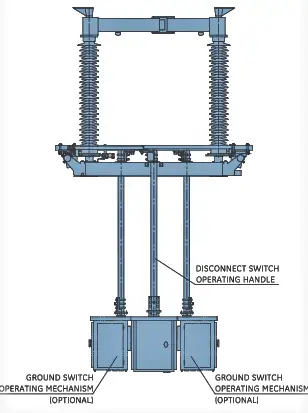
Operating Mechanisms in Disconnect Switch
For some disconnect switches, single-phase or three-phase operation is possible. A three-phase disconnect switch is usually equipped with operating mechanisms that allow it to be opened and closed from the ground level by an operator standing at the level of the switch.
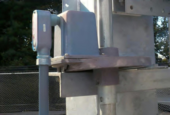
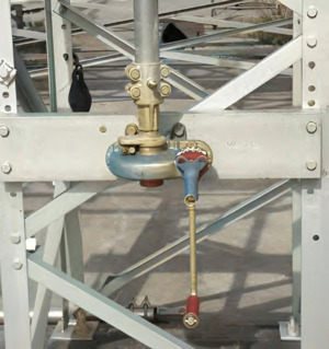
1. Manual Operating Mechanisms
There are several types of manual operating mechanisms. Swing handles and gear cranks are commonly used. Handwheels or reciprocating handles are less common manual operating mechanisms.
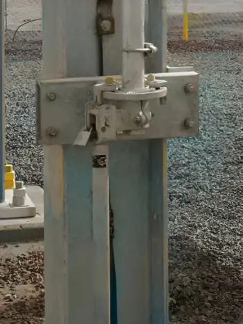
The choice of which manual operating mechanism to use is made based upon the required amount of applied force necessary to permit operation of the disconnect switch.
There is a general rule of thumb that disconnect switches rated 69kV or below or 1200A continuous current and below are usually equipped with a swing handle. While disconnect switches rated above 115kV and 1600A continuous current are usually equipped with gear crank operating mechanism. Depending on the type of disconnect switch used, this convention can vary. Different types of disconnect switches require different amounts of force to operate.
2. Motor Operating Mechanisms
A motor-operated switching mechanism is also available and is used when remote switching is necessary or desirable. Typically, it’s used when the switch is part of a comprehensive system monitoring scheme, like a supervisory control and data acquisition system (SCADA).
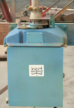
The motor-operated mechanisms are either powered by the substation battery or by auxiliary AC power. There are some motor-operated mechanisms that have their own internal batteries that can be charged by an auxiliary AC source via a AC to DC trickle charger. This provides multiple stored operations in the event of an auxiliary AC power failure.
For substations without a control building to store substation batteries, these stored energy motor operators are ideal. They are also useful in line installations where it is not economically feasible to provide the motor operator with a DC battery source outside of the motor.
To control a stored energy motor operator remotely, a remote terminal unit supplies an electrical signal that triggers the motor operator.
Types of Disconnect Switches
A disconnect switch can be mounted in a variety of positions, the most common of which are horizontal upright, vertical, and underhung. It can be designed to operate horizontally or vertically based upon how their switch blades are mounted on the switch.
There are several types of disconnect switches available based on their configuration, including
- Vertical break
- Double end break (also sometimes called double side break)
- Double end break “Vee” (also sometimes called double side break “Vee”)
- Center break
- Center break “Vee”
- Single side break
- Vertical reach (also sometimes called pantograph, semipantograph, or knee-type switches)
- Grounding
- Hook stick
The different types of disconnect switches have specific features that suit different applications. Load break switch is another type of disconnect switch.
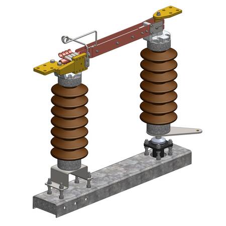
1. Vertical break disconnect switch
Vertical break switches are the most widely used design. They are the most versatile design, and can be installed with minimum phase spacing.
They are excellent for use in ice environments due to their rotating blade design. Their contact design makes them ideal for installations in locations with high fault currents.
2. Double end break disconnect switch
Double end break switches can be installed on minimum phase spacing (the same phase spacing as for vertical break switches due to the disconnect switch blades being disconnected from both the source and the load when in the open position.
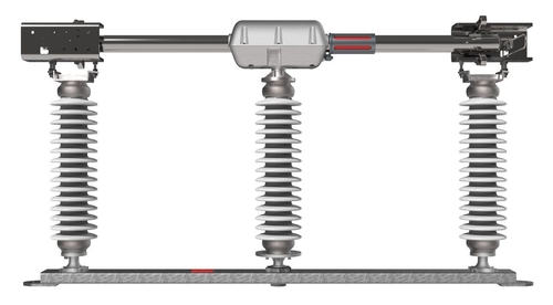
They can be installed in locations with low overhead clearance (something vertical break switch designs cannot do). Because the blades do not need to be lifted during operation, they do not require a counterbalance (many vertical break switches rely on counterbalance springs to reduce operating effort and control blade movement during opening and closing operations).
Due to their rotating blade design, double end break switches are excellent for applications in ice environments (even better than vertical break switches due to the contact configuration of the double end break switch versus the vertical break switch).
Due to their contact design, they are ideal for installations in areas with high fault currents. In addition, they have the advantage of interrupting significantly more line charging current and magnetizing current than a single break switch because they have two breaks per phase.
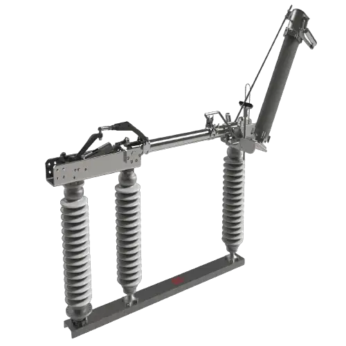
3. Double end break “Vee” disconnect switch
Double end break “Vee” switches share all of the same characteristics as conventional double end break switches but with an additional feature. Additional features of this switch include consuming the smallest amount of substation space of any three-phase switch.
They can be mounted on horizontal beams with one, two, or three vertical columns (depending on the kilovolt rating of the switch and other site-specific conditions such as seismic considerations).
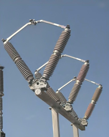
4. Center break disconnect switch
A center break switch can be installed in a minimum overhead clearance location, but it requires a greater phase spacing than a vertical break switch, a double end break switch, or a double end break “Vee” switch. It is because center break switches have one of the two blades per phase energized when in the open position.
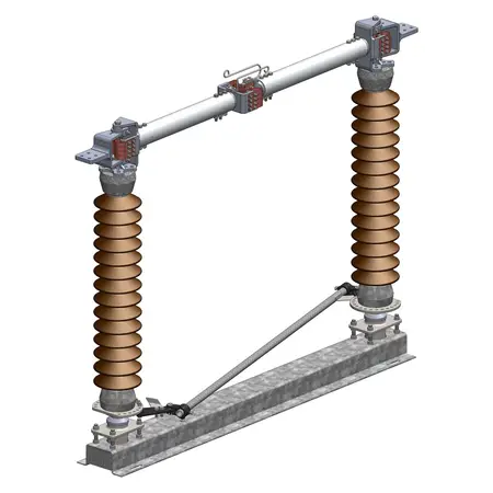
It requires only six insulators per three-phase switch (versus the nine insulators per three-phase switch required for vertical break, double end break, and double end break “Vee” switches).
Center break switches do not require a counterbalance for the blades as the blades do not have to be lifted during operation.
They are the best available three-phase switch design for vertical mounting as the two blades per phase self-counterbalance each other during opening and closing operations via the synchronizing pipe linkage.
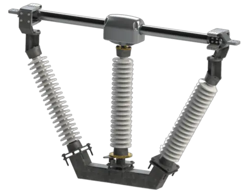
5. Center break “Vee” disconnect switch
As with conventional center break switches, “Vee” switches share many of the same characteristics, but they require less space in the substation.
The reason for this is that they can be installed on a single horizontal beam structure with one, two, or three vertical columns.
6. Single side break disconnect switch
The single side break switch can be installed in locations with minimal overhead clearance, but may require more phase spacing than vertical break, double end break, or double end break “Vee” switches.
They require only six insulators per three-phase switch (versus the nine insulators per three-phase switch required for vertical break, double end break, and double end break “Vee” switches)
They do not require a counterbalance for the blades since they do not have to be lifted during operation.
7. Vertical reach disconnect switch
Vertical reach switches are used most commonly in extra high-voltage (EHV) applications, typically for 345, 500, and 765 kV installations.
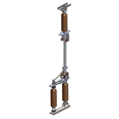
In the US utility industry, vertical reach switches are rare, but in Europe and elsewhere, they are fairly common.
8. Grounding switch
A grounding switch can be integrated into any of the previously mentioned disconnect switch types or can be installed as a stand-alone device (i.e., not attached as an integral component of a disconnect switch).
The purpose of grounding switches is to ensure the safety grounding of disconnect switches, buses, and capacitor banks. Grounding switches, as previously mentioned, are normally equipped with an interlocking scheme to ensure proper operation sequence.
9. Hook stick switch
A hook stick switch is a single-phase device that provides isolation, bypassing (usually for a regulator, recloser, or a current transformer), transferring (i.e., feeding the load from an alternate source), or grounding.
Disconnect Switch Standards
For all types of disconnect switches previously mentioned, phase spacing is usually adjusted to satisfy the spacing of the bus system in the substation. Depending on the switch type and kV rating, the standards establish minimum metal-to-metal clearances to ensure proper electrical performance.
Before about 1970, almost all switches had copper live parts and met a standard allowing a 30°C temperature rise when energized and carrying its full nameplate current value. Since 1970, many switch designs have been created using aluminum live parts and a new governing standard allows a 53°C temperature rise when the switch is energized with its full current.
In accordance with international standards, switches with full nameplate current ratings can rise by 65°C. When it comes to temperature rise capability, cooler switches are better, as they have more inherent current carrying capacity. So a 30°C rise switch will be more capable than a 53°C rise switch or a 65°C rise switch, and a 53°C rise switch will be more capable than a 65°C rise switch.

Comments are closed.