This article explains the measurement of three-phase power in star connected or delta connecter load using the wattmeter methods.
The power in a three phase load can be measured by following methods:
- Three wattmeter method
- Two wattmeter method
- One wattmeter method
The name of these methods indicates the number of wattmeters used in the measurement of the three-phase power.
What is a Wattmeter?
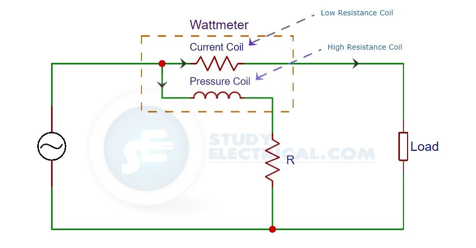
A wattmeter is an equipment used to measure power in a circuit. It consists of two types of coils. They are:
- A Current Coil that possesses a low resistance.
- A Pressure or Potential Coil that possesses a high resistance.
The current coil is connected in series with the line carrying current. The pressure coil is connected across the two points whose potential difference is to be measured. Refer the figure for the connections of a wattmeter.
A wattmeter shows a reading which proportional to the product of three values. They are
- Current (I) through its current coil.
- Potential difference (V) across its pressure coil.
- Cosine of the angle between voltage and current (Cosϕ).
P = VICos(ϕ)
A comparison between the methods of measuring power in a three-phase circuit is shown in the table below.
| Three Wattmeter Method | Used for measurement of 3 phase, 4 wire circuits. Both balanced and unbalanced loads. |
| One Wattmeter Method | Used in Balanced 3 phase, 3 wire load circuit. |
| Two Wattmeter Method | Used in both balanced and unbalanced 3 phase, 3 wire circuits |
Three Wattmeter Method
Now we will explain the measurement three-phase power measurement using three wattmeter method.
Three wattmeter method is used to measure power in 3 phase, 4-wire circuits. However, this method can also be used in 3 phase, 3 wire delta connected load, where power consumed by each load is required to be determined separately.
The figure below shows the three wattmeter connection of 3 phase, 4 wire star connected load.
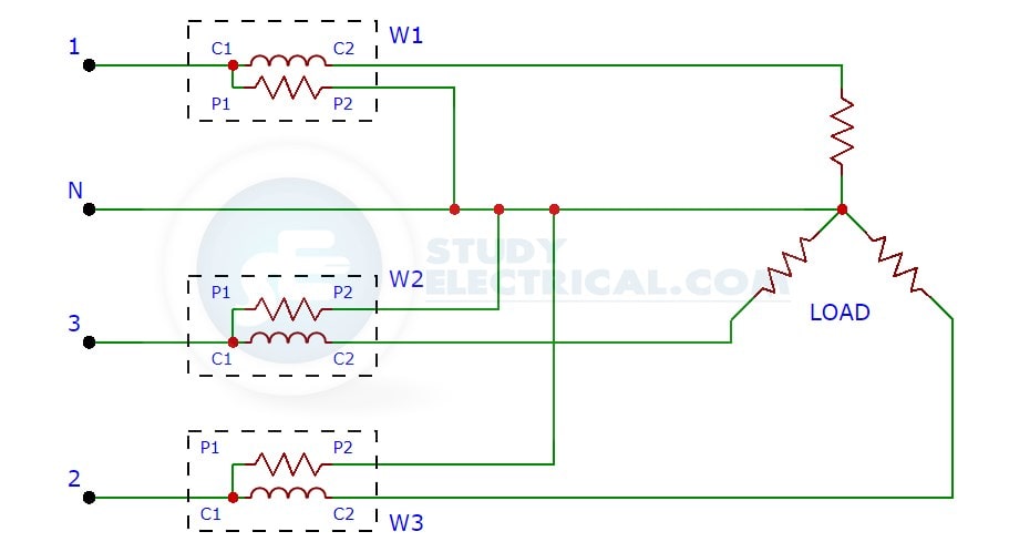
As indicated in the figure, the three wattmeters are connected in each of the three phases to measure three-phase power usage of the load whether star or delta connected.
The current coil of each wattmeter carries the current of one phase only and the pressure coil measures the phase voltage of the phase. Hence, each wattmeter measures the power in a single phase. The total power in the load is given by the algebraic sum of the readings of the three wattmeters.
P = W1 + W2 + W3
where , W1 = V1*I1 , W2 = V2*I2, W3 = V3*I3
Disadvantages of Three Wattmeter Method
While using three wattmeter method following difficulty is met with:
- In the case of 3 phase, 3 wire star connected load, it is difficult to get a neutral point which is required for connection. In special cases, when this method is necessary to use, an ‘artificial star’ can be formed.
- In case of delta connected circuits, the difficulty in using this method is due to fact that the phase coils are required to be broken for inserting current coils of wattmeters.
To measure power it is not necessary to use three wattmeter, even two wattmeters can be used for the purpose.
Except for 3 phase, 4 wire unbalanced load, three-phase power are measured using only Two Wattmeter Method.
One Wattmeter Method
The next method we are going to discuss is the one wattmeter method.
In this method of three-phase power measurment, the current coil is connected in any one line and the pressure coil is connected alternatively between this and the other two lines. The connection diagram is shown in the figure below.
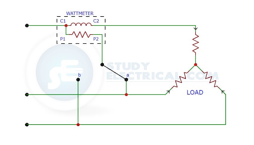
So we will get two readings for a balanced load. The two readings so obtained, correspond to those obtained by the normal two wattmeter method.
A balanced load is a load that draws the same current from each phase of the three-phase system, while an unbalanced load has at least one of those currents different from the rest.
In balanced 3-wire, 3-phase load circuit the power in each phase is equal. Therefore, the total power of the circuit can be determined by multiplying the power measured in any one phase by three.
Total power in balanced load = 3 x Power per Phase
= 3 x Wattmeter reading
Disadvantages of One Wattmeter Method
This method is not of as much universal application as the two wattmeter method because it is restricted to fairly balance loads only. Even a slight degree of unbalance in the loading produce a large error in the measurement.
However, it may be conveniently applied, for instance, when it is desired to find the power input to a factory motor in order to check the load up on the motor.
Two Wattmeter Method
As the name indicates, in this method two wattmeters are used to measure three-phase power. This is the most popular method among the three.
This method is generally used for the measurement of power in 3 phase, 3-wire load circuits. It can be used to measure power in star/delta connected load in balanced or unbalanced condition.
Remember a balanced load is a load that draws the same current from each phase of the three-phase system, while an unbalanced load has at least one of those currents different from the rest.
In two wattmeter method, the current coils of the two wattmeters are inserted in any two lines and pressure coil of each wattmeter is joined to the third line. Refer the figure below for better understanding.
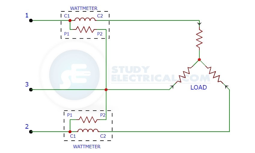
The figure above shows the two wattmeter connection of star connected load. Similarly, delta connected loads are also used. Two wattmeter method can be used irrespective of balanced or unbalanced load.
The algebraic sum of two wattmeter reading gives the total power in the 3-phase, 3 wire star-connected or delta connected load circuits whether the load is balanced or unbalanced.
P = W1 + W2