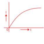
A current limiting reactor, also known as a series reactor, is an inductive coil with a large inductive reactance compared to its resistance. It is used to limit short-circuit currents during fault conditions.
Need of Current Limiting Reactor in Power System
With the fast-expanding power system, the fault level (i.e., the power available to flow into a fault) is also rising. The circuit breakers connected in the power system must be capable of dealing with the maximum possible short-circuit currents that can occur at their points of connection. Generally, the reactance of the system under fault conditions is low, and fault currents may rise to a dangerously high value. If no steps are taken to limit the value of these short-circuit currents, not only will the duty required of circuit breakers be excessively heavy, but also damage to lines and other equipment will almost certainly occur.
Use of current limiting reactor,
(1) to limit the fault current,
(2) to limit inrush current during a capacitor switching
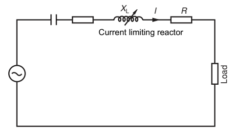
In order to limit the short-circuit currents to a value that the circuit breakers can handle, additional reactances known as reactors are connected in series with the system at suitable points. A reactor is a coil with a number of turns designed to have a large inductance compared to its ohmic resistance. The forces on the turns of these reactors under short-circuit conditions are considerable, and therefore, the windings must be solidly braced. It may be added that due to the very small resistance of reactors, there is very little change in the efficiency of the system.
Current Limiting Reactor Working
Current limiting reactors are connected in feeders and ties, generator leads, and between bus sections to reduce the magnitude of short-circuit currents. They allow for free interchange of power under normal conditions, but during a fault, the disturbance is confined to the faulty location. Since the resistance of the reactors is small compared to their reactance, the system’s efficiency is not significantly affected.
Short-circuit current is reduced by increasing the system’s reactance, and it depends on factors like generating capacity, voltage at the fault point, and the total reactance between the generating point and the fault location. The breaking capacity of a circuit breaker depends on the magnitude of the fault current. If the fault current exceeds the breaker’s designed limit, it cannot be extinguished. Therefore, in large interconnected power systems with many generators and motors, faults can lead to fault currents exceeding the breaker’s capacity. To address this issue, reactors are strategically placed to limit short-circuit currents at different points.
Current limiting reactors are inductive coils with large inductive reactance compared to resistance, and they are used to limit short-circuit currents during faults. They also help reduce voltage disturbances in the rest of the system. These reactors are installed in feeders, ties, generator leads, and between bus sections to reduce short-circuit currents and the associated voltage disturbances. While they allow normal power interchange, they restrict disturbances to the faulty section during a fault because their resistance is much smaller than their reactance. This setup minimizes the impact on the overall system’s efficiency.
Construction of Current Limiting Reactor
Current limiting reactors are constructed with specific design considerations to ensure their proper functioning in electrical systems. Here are the key aspects of their construction:
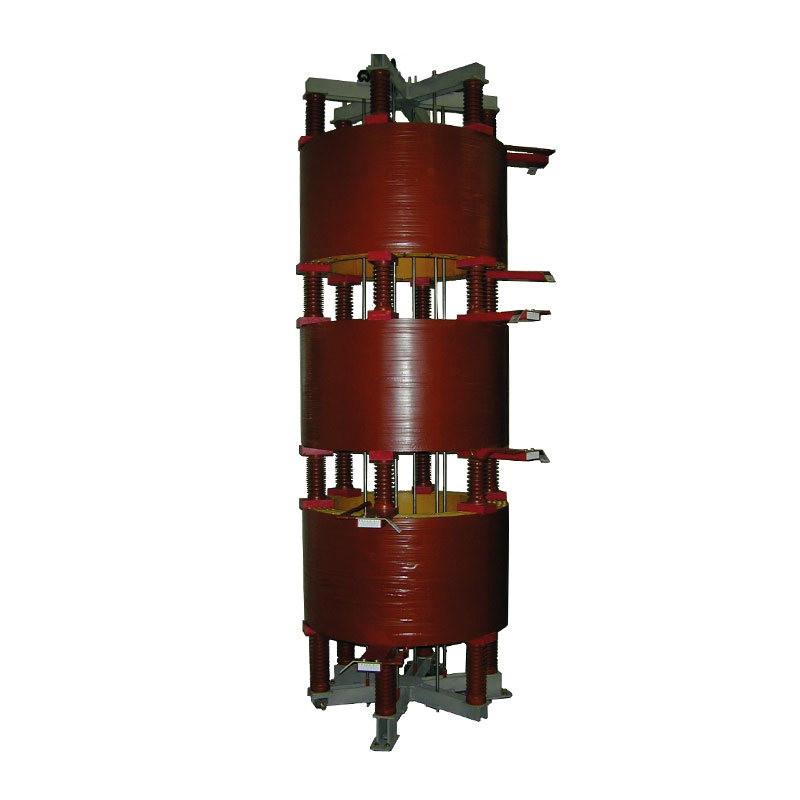
Coil Configuration: These reactors typically consist of three-phase coils stacked one above the other, with support insulators placed between them. The design helps maintain adequate spacing (>300 mm) between the coils, ensuring that each coil operates independently without significant inductive interference from the others.
Foundation Considerations: The foundation of the reactor coil is crucial. It should be constructed to have no closed loops in the reinforcement concrete steel (RCC). This design feature minimizes the potential for unwanted magnetic interactions or interference.
Installation Locations: Current limiting reactors can be installed in various locations within the electrical system. They may be introduced in outgoing feeders, incoming feeders, or between bus couplers, depending on the specific system requirements and load-sharing needs.
Connection Types: These reactors can have fixed or variable reactance and can be designed with either linear (fixed reactance) or nonlinear magnetic characteristics as needed. Linear reactors, especially fixed reactance ones, are preferred when limiting inrush currents is required during startup.
Reactance Stability: One essential requirement for current limiting reactors is that their reactance should not diminish due to saturation effects during fault conditions. This stability is necessary to effectively limit short-time fault currents.
Core Type: Current limiting reactors can be designed with different core types. Ideally, they should have a no-iron circuit and may be of air core or coreless type. Coreless reactors are preferred for applications requiring near-constant reactance at all currents since they lack an iron core that can cause nonlinear saturating characteristics.
Gapped Iron Core Reactors: Some reactors use gapped iron cores, where an air gap or non-magnetic material is introduced between the core laminations. This design raises the saturation level to provide adequate impedance during faults. Gapped iron core reactors can serve as current limiters in certain applications.
Voltage Considerations: While designing reactors, it’s crucial to ensure that the voltage available across the load does not fall below permissible levels due to voltage drops across the reactors. Reactors designed for these applications should be continuously rated to maintain voltage stability.
In summary, the construction and design of current limiting reactors are critical aspects that depend on the specific requirements of the electrical system and the desired performance characteristics of the reactor. Proper construction ensures their effectiveness in limiting fault currents and maintaining system stability.
Functions of Current Limiting Reactor:
The main function of a current limiting reactor is to maintain its reactance even when a large short-circuit current flows through its windings. When the fault current exceeds about three times the rated full-load current, a large cross-section iron-cored reactor is used to limit the fault current. However, iron-cored reactors are costly and heavy due to their large cross-sectional area. Therefore, air-cored reactors are commonly used to limit short-circuit or fault currents. Iron-cored reactors produce hysteresis and eddy current losses, resulting in higher power consumption compared to air-cored reactors. Typically, in an air-cored reactor, the total losses are around 5% of the KVA rating of the reactor.
So the functions of current limiting reactor can be pointed out as below,
- Reducing the flow of short-circuit current to protect appliances from mechanical stress and overheating.
- Minimizing the magnitude of voltage disturbances caused by short circuits.
- Limiting fault currents from spreading into healthy feeders or parts of the system, increasing the chances of continuity of supply.
Drawbacks of current limiting reactors:
- Increasing the total percentage reactance of the circuit when installed, which can lead to increased reactive voltage drop.
- Decreasing the power factor and resulting in poorer system regulation due to an increased angle of lag.
Advantages:
- Protective reactors safeguard apparatus from excessive mechanical stresses and overheating, thus protecting the entire system.
- They reduce voltage disturbances caused by short circuits.
- These reactors localize faults by limiting the current flowing into the fault from other healthy feeders or parts of the system, preventing the fault from spreading.
- They help reduce the duty imposed on switching equipment during fault conditions.
Disadvantages:
- The installation of current limiting reactors increases the total percentage reactance of the system, leading to higher reactive voltage drop and a decrease in power factor, resulting in poorer system regulation due to an increased angle of lag.
Location of Current Limiting Reactors
Short circuit current limiting reactors can be placed in various locations, including
- in series with each generator,
- in series with each feeder,
- in bus-bars.
It is difficult to make a definitive statement about which of these locations is preferable, as each installation has its unique requirements that must be thoughtfully considered before deciding on the reactor’s placement.
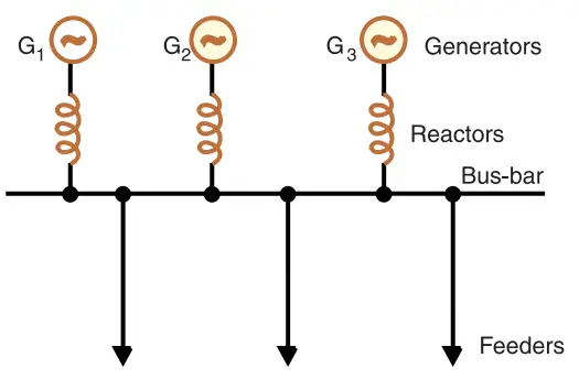
1. Generator Reactors
Definition: When reactors are connected in series with each generator, they are referred to as generator reactors. These reactors act as a part of the leakage reactance of the generator, providing protection in case of short-circuits beyond the reactors.
Disadvantages
- Constant Voltage Drop and Power Loss: Generator reactors introduce a constant voltage drop and power loss, even during normal operation.
- Generator Synchronization Risk: If a bus-bar or feeder fault occurs in close proximity to the bus-bar, the voltage at the bus-bar can drop to a low value, potentially causing the generators to fall out of synchronization.
- Supply Continuity Impact: In the event of a fault occurring on any feeder, the continuity of supply to others is likely to be affected.
Considerations
Modern power station generators typically have sufficiently large leakage reactance to protect them against short-circuits. Therefore, it is not a common practice to use separate reactors for the generators due to the mentioned disadvantages.
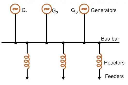
2. Feeder Reactors
Definition: Feeder reactors are reactors connected in series with each feeder. They are commonly used in electrical systems since most short-circuits tend to occur in feeder circuits.
Advantages:
- Voltage Stability: One key advantage of feeder reactors is that they help maintain voltage stability. When a fault occurs on any feeder, the voltage drop within its corresponding reactor does not significantly affect the voltage at the bus-bars. This minimizes the risk of generators losing synchronization.
- Localized Fault Effects: Faults on one feeder do not propagate to affect other feeders. Consequently, the effects of a fault are localized and do not disrupt the entire system.
Disadvantages:
- Constant Power Loss and Voltage Drop: Feeder reactors introduce a constant power loss and voltage drop, even during normal operation.
- Lack of Generator Protection: Feeder reactors do not provide protection to generators in the event of a short-circuit at the bus-bars. However, such faults are rare, and modern generators have significant leakage reactance to withstand short-circuits across their terminals.
- Sizing Challenges: If the number of generators in the system increases, the size of feeder reactors may need to be increased to keep short-circuit currents within the ratings of the feeder circuit breakers.
3. Bus-Bar Reactors
Bus-bar reactors are a method of locating reactors in an electrical system, addressing the disadvantages associated with other placement methods. There are two primary methods for this purpose: the Ring system and the Tie-Bar system.
Ring System
In the Ring system, the bus-bar is divided into sections, and these sections are connected through reactors. Typically, one feeder is supplied by one generator.
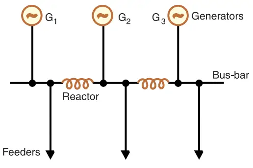
Under normal operating conditions, each generator supplies its designated load section, resulting in minimal power loss and voltage drop in the reactors. The principal advantage of this system is that in the event of a fault occurring on any feeder, only the generator connected to that particular feeder primarily feeds the fault current. The presence of reactors limits the current fed from other generators. Therefore, only the section of the bus-bar connected to the faulty feeder is affected, while the other sections can continue normal operation.
Tie-Bar System
In the Tie-Bar system, there are effectively two reactors in series between sections of the bus-bar. These reactors need to have approximately half the reactance of those used in a comparable Ring system.
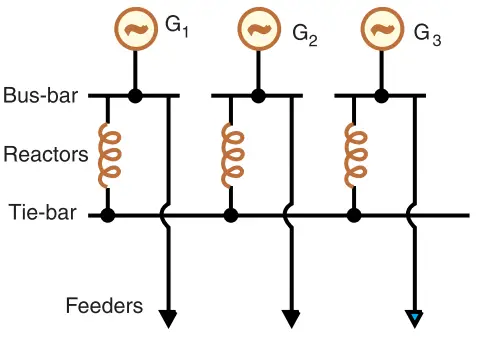
An advantage of the Tie-Bar system is that additional generators can be connected to the system without requiring changes in the existing reactors. However, this system has the drawback of requiring an additional bus-bar, known as the tie-bar.
By using Bus-Bar reactors, the voltage drop and power loss in reactors during normal operation can be significantly reduced, making them an effective solution for maintaining system stability.