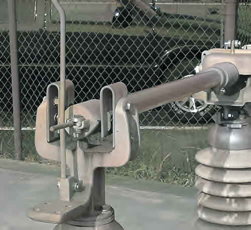
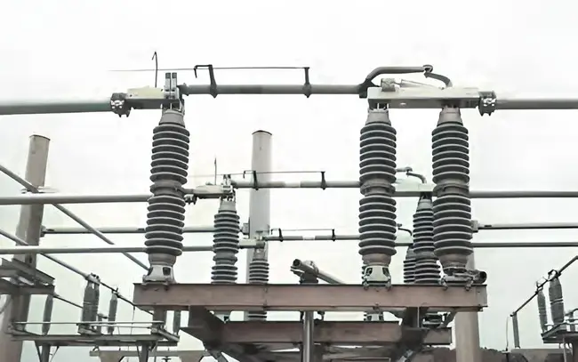
Load break switches are essential components within electrical substations. These switches play a vital role in managing electrical currents by safely disconnecting and reconnecting circuits. To comprehend their significance and how they function, it’s essential to delve into the world of load break switches.
In this article, we’ll explain what load break switches are and explore their various components, including arcing horns and interrupters. We’ll also discuss how to determine the specific attachments needed for different scenarios, ensuring the safety and reliability of electrical systems. So, let’s begin our journey into the world of load break switches and uncover their critical role in electrical substations.
What Are Load Break Switches?
Load break switches, often found in electrical substations, serve a fundamental function in ensuring the smooth operation of power systems. Let’s break down what these switches are all about:
Fundamental Function:
Load break switches are essentially disconnect switches that have been specially designed to do something crucial – they can safely interrupt and restore specific electrical currents. In simple terms, they help control the flow of electricity. When it’s time to stop the current, they open up, creating a gap that halts the flow. When it’s time to resume the current, they close, re-establishing the connection.
Enhancing Performance:
Now, to make these switches work even better, they come equipped with additional equipment. This equipment serves to improve their overall performance. It’s like adding turbo boosters to a car. It could be things like arcing horns or quick break whip horns. These enhancements increase the speed at which the metal parts of the switch make and break contact. Essentially, they make the switch more efficient and safer.
Metal-to-Metal Contact:
Here’s where things get a bit technical but stick with us. When a load break switch opens and closes, metal parts are involved. These metal-to-metal contacts are crucial because they determine how well the switch can do its job. They need to be just right. If they’re not, it can lead to problems like electrical arcing. But don’t worry; we have solutions for that too, like confining the arcing in a chamber with a safe dielectric medium. It’s all about ensuring that the switch operates reliably and safely.
So, that’s the lowdown on load break switches and their basic functions. Next, we’ll explore the different types of equipment that make them even more effective.
Types of Equipment Enhancing Load Break Switches
Now that we’ve grasped the fundamental function of load break switches, let’s dive deeper into the types of equipment that supercharge these switches and make them even more efficient:
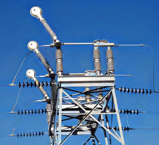
1. Arcing Horns
Imagine you have a load break switch, and it needs to handle very small amounts of charging or magnetizing current. That’s where arcing horns come into play. These are like the special tools for the job. Arcing horns are made from materials like copper or stainless steel. Their role is to help interrupt those small currents safely. However, it’s important to note that standard arcing horns aren’t designed for load breaking. Using them for this purpose can harm the switch. Also, they don’t have a loop splitting rating.
2. High-Speed Arcing Horns
Sometimes, we need to interrupt small currents really quickly. For this task, high-speed arcing horns, often called quick break whip horns, come to the rescue. These horns are made from materials like stainless steel or beryllium copper. They work by separating rapidly from the fixed catcher on the switch’s jaw contact assembly. Quick break whip horns are suitable for use in disconnect switches rated up to 161 kV, but be cautious; at higher voltages, they can produce visible or audible corona. Like standard arcing horns, quick break whip horns aren’t designed for load breaking and have no loop splitting rating.
So, these enhancements, whether standard arcing horns or high-speed versions, help load break switches handle specific types of currents more effectively. But what if we need to do more than just interrupting currents? That’s where load/line/loop interrupters come into the picture. We’ll explore these in the next section.
Load/Line/Loop Interrupters
Load break switches are versatile, but sometimes, they need a little extra help when it comes to dealing with currents. That’s where load/line/loop interrupters come into play. Let’s explore them in more detail:
Load/Line/Loop Interrupters: These are specialized additions to disconnect switches, designed to handle a range of electrical currents. They can effectively interrupt loop currents, load currents, or significant amounts of line charging current. The interruption duty depends on the type of interrupter, which can use either sulfur hexafluoride (SF6) gas or vacuum as the interrupting medium.
SF6 Gas Interrupters: These are commonly used in load break switches and work as single gap interrupters for all voltage ratings. This means they don’t require multiple gaps per phase to interrupt the current successfully. SF6 gas interrupters also offer a visual indication of adequate dielectric for safe interruption, a crucial safety feature, especially for manually operated load break switches.
Vacuum Interrupters: Vacuum interrupters are used for system voltages above 30 kV. Unlike SF6 gas interrupters, they are multiple gap interrupters, requiring a specific number of vacuum bottles per phase depending on the voltage rating. For example, at 69 kV, you’d need three vacuum bottles per phase. However, vacuum interrupters lack the visual indication feature present in SF6 gas interrupters.
These load/line/loop interrupters add another layer of functionality to load break switches, making them capable of handling a broader range of currents and ensuring the safety and reliability of the electrical system.
In the next section, we’ll explore how to determine which of these attachments (arcing horns, quick break whip horns, or load/line/loop interrupters) is needed for a specific installation, considering factors like charging current and magnetizing current.
Determining Attachment Requirements
Choosing the right attachment for a load break switch installation is crucial. To do that, we need to consider factors like charging current and magnetizing current. Let’s delve into this aspect:
Calculating Charging Current:
The amount of charging current in a given installation depends on several factors, including the system’s voltage rating and various environmental conditions. To estimate the available line charging current at a particular voltage rating, you can use industry guidelines. For instance:
- At 15 kV, it’s approximately 0.06 A/mile of line.
- For 23 kV, it’s around 0.10 A/mile of line.
- At 34.5 kV, it increases to about 0.14 A/mile of line.
- And so on, with higher voltages having higher values.
Keep in mind that real-world conditions, such as phase spacing, atmospheric conditions, adjacent lines, and conductor configurations, can influence the actual charging current in an installation.
Magnetizing Current Estimation
When it comes to magnetizing current, you can make a conservative estimate by considering it to be approximately 1% of the full-load rating of the power transformer. However, in most cases, the actual magnetizing current is significantly less. For precise values, it’s advisable to consult the manufacturer of the power transformer.
In essence, determining the right attachment for a load break switch involves understanding the charging and magnetizing currents specific to your installation. While industry standards can provide conservative estimates, consulting with experts or manufacturers for precise data is always a wise approach. These considerations ensure that the load break switch operates effectively and safely in your electrical system.
In the following section, we’ll explore the various factors influencing the amount of available magnetizing current in more detail.
Factors Affecting Magnetizing Current
Now, let’s take a closer look at the factors that influence the amount of available magnetizing current, a critical aspect in load break switch installations:
1. Transformer Core Design: The design of the transformer’s core plays a significant role in determining magnetizing current. Different core designs can result in varying levels of magnetization.
2. Transformer Core Material: The material used in the core also matters. Different core materials have distinct magnetic properties that affect the magnetizing current.
3. Transformer Coil Design: How the coils are wound within the transformer can impact magnetizing current. Coil design affects the magnetic field generated.
4. Transformer Coil Material: The material used in the coils, such as copper or aluminum, affects their electrical properties and, consequently, the magnetizing current.
Understanding these factors allows for a more precise estimation of magnetizing current in your specific transformer installation. While we often use a conservative 1% estimate for general calculations, reaching out to the manufacturer can provide you with the actual magnetizing current value, which may be considerably less.
Just as various factors influence the amount of available line charging current, a multitude of considerations impact the available magnetizing current in your electrical system. Being aware of these factors ensures that load break switches are equipped to handle the unique conditions of your installation.
Conclusion
In the world of electricity, load break switches are like the traffic controllers, making sure everything runs smoothly. They can stop and start the flow of electricity when needed. To make them even better at their job, they have special helpers like arcing horns and quick break whip horns. These helpers make sure the switches work fast and safely.
But it’s not just about stopping and starting electricity; sometimes, these switches need to handle different types of electrical currents. That’s where load/line/loop interrupters come in. They give these switches superpowers to deal with all sorts of electrical challenges.
Choosing the right helper for a switch isn’t easy; it depends on things like how much electricity is involved. It’s like picking the right tool for a job. By understanding these switches and their helpers, we can keep our electricity safe and reliable, making our world a little brighter.