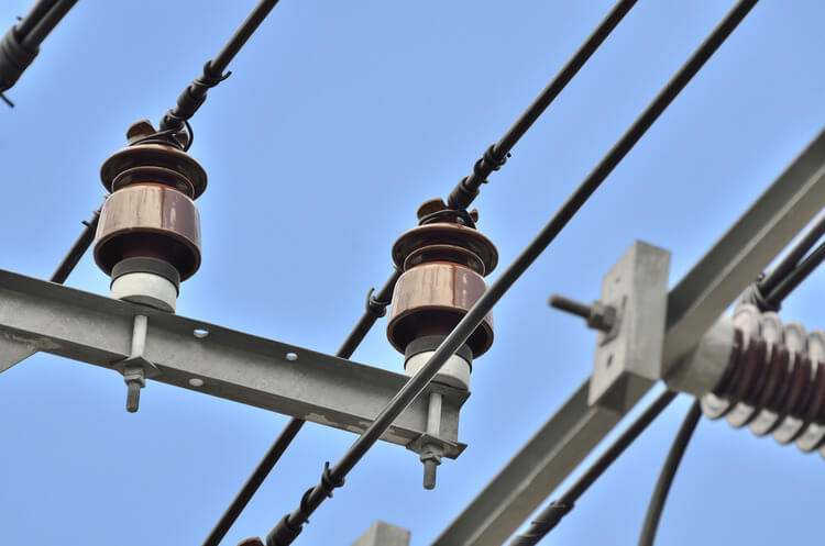
Pin type insulators are a critical component of electrical transmission systems, ensuring the safe and efficient transmission of electricity. Designed to withstand high voltages, these insulators provide insulation between overhead power lines and supporting structures.
In this article, we will explore the features, working principles, and applications of pin type insulators, highlighting their significance in the field of electrical power transmission.
Additionally, we will delve into technical aspects such as voltage ratings, leakage distance, composite insulators, flashover performance, creepage distance, pollution performance, mechanical strength, and electric field distribution.
Features and Construction
Pin type insulators possess several key components that enable them to perform their function effectively. They feature a metallic pin, usually made of galvanized steel or non-corrosive materials, which acts as a conductor for transmitting electrical energy. The pin securely attaches to the insulator body, typically made of porcelain or composite materials, providing mechanical support and electrical insulation.
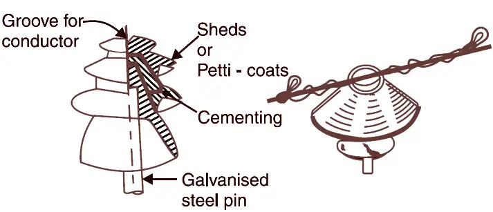
The insulator body consists of multiple insulating units, or sheds, strategically designed to enhance the insulator’s electrical performance. These sheds are arranged in a circular or petticoat pattern, maximizing surface distance and minimizing the risk of electrical discharge or arcing. Additionally, the insulator is equipped with a base, often made of cement or resin, to provide mechanical stability and facilitate installation on the supporting structure.
Working Principle
The primary function of pin type insulators is to prevent electrical current from flowing through the supporting structure and divert it safely to the ground. This is achieved through the insulating properties of the porcelain or composite material used in their construction. These materials have high resistance to electricity, effectively isolating the conductive pin from the supporting structure.
When the pin type insulator is installed on a tower or pole, the electrical current flows through the conductor (the metallic pin) and reaches the insulator body. The insulating material resists the flow of current, ensuring that it cannot pass through to the supporting structure. Instead, the current is diverted along the pin and safely grounded, preventing any damage or electrical hazards.
Technical Considerations
Pin type insulators are designed to cater to specific voltage requirements. For power distribution systems with voltages up to 33kV, pin insulators are commonly used. These insulators are placed on the cross arm of the supporting tower and have grooves on the upper end to hold the conductor securely. The conductor is tied to the insulator using annealed binding wire of the same material as that of the conductor. A lead thimble is cemented into the insulator body to receive the pin.
In terms of material, pin insulators utilize non-conducting materials such as porcelain, ceramic, silicon rubber, or polymers. It is important to note that polymer pin insulators tend to be heavier compared to porcelain insulators.
For low voltage applications, single-piece pin insulators are sufficient, while high voltage requirements may require two or more pieces of insulators cemented together to maintain the required insulation thickness. These insulators provide an adequate path for leakage current, ensuring efficient performance.
Voltage Ratings: Pin type insulators are available in a wide range of voltage ratings to accommodate various transmission system requirements. They can withstand low, medium, or high voltage levels, typically ranging from a few hundred volts to several hundred kilovolts. Commonly used for power distribution systems with voltages up to 33kV.
Leakage Distance: The leakage distance is the shortest path along the insulator’s surface between the conductor and the supporting structure. It plays a crucial role in determining the insulator’s ability to withstand electrical stress and prevent leakage current. Insulators with longer leakage distances offer improved performance in areas with high contamination or pollution levels.
Composite Insulators: In recent years, composite insulators have gained popularity as alternatives to traditional porcelain insulators. These insulators consist of a fiberglass rod core and an outer silicone rubber housing. They offer advantages such as lighter weight, improved resistance to vandalism and seismic activities, and better pollution resistance.
Flashover Performance: Flashover is a critical phenomenon where an electrical discharge occurs across the insulator’s surface due to contaminants or high electrical stress. Pin type insulators are designed to minimize the risk of flashover through shed profiles, adequate creepage distance, and hydrophobic properties that repel moisture and pollutants. The wavy structure of pin insulator increases its flashover voltage.
Creepage Distance: Creepage distance refers to the surface distance between two successive sheds or between the conductor and the supporting structure. It is crucial for resisting leakage current and maintaining electrical isolation. Longer creepage distances are desirable in polluted or humid environments to prevent tracking and arcing.
Pollution Performance: Pin type insulators used in areas with high pollution levels require specific designs to withstand pollution-induced flashovers. Features like hydrophobic surfaces, self-cleaning properties, and periodic cleaning help maintain the insulator’s electrical performance in such environments.
Mechanical Strength: Pin type insulators must possess sufficient mechanical strength to withstand environmental stresses, including wind, ice, and other factors. Mechanical failures can compromise the insulator’s electrical performance and pose safety hazards. The design and material selection of pin type insulators account for these mechanical requirements to ensure long-term reliability.
Electric Field Distribution: Pin type insulators are engineered to maintain a uniform distribution of electric field along their surface. This uniform distribution helps prevent localized areas of high electrical stress, reducing the likelihood of electrical breakdown or flashover.
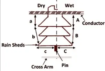
Flashover voltage, which refers to the voltage at which an electrical discharge occurs across the insulator surface, is influenced by factors such as surface condition. The flashover voltage for moist and dirty surfaces is generally lower than that for clean and dry surfaces. The total dry arcing distance is the sum of all the direct distances through the air, denoted by (a+b+c). On the other hand, the total wet arcing distance is represented by (A+B+C).
Applications
Pin type insulators are widely used in various electrical transmission systems, ranging from low voltage distribution lines to high voltage transmission lines. They find application in both overhead line networks and substations. The choice of insulator depends on the voltage level, environmental conditions, and mechanical requirements of the specific application.
Pin type insulators are particularly suited for medium and high voltage lines, where they offer excellent electrical insulation and mechanical strength. They are commonly found in power distribution networks, connecting transformers, and transmission lines to residential and industrial areas. Moreover, pin type insulators are extensively used in substation equipment such as circuit breakers, isolators, and busbars, ensuring the safe and reliable operation of these critical components.
Advantages and Maintenance
They are the earliest developed overhead insulator compared to shackle insulator, but are still commonly used in power networks up to 33 kV system. Pin type insulator can be one part, two parts or three parts type, depending upon application voltage. In a 11 kV system we generally use one part type insulator where whole pin insulator is one piece of properly shaped porcelain or glass.
Pin type insulators offer several advantages that make them a preferred choice in electrical transmission systems. They exhibit high mechanical strength, allowing them to withstand significant loads and stresses, including wind, ice, and mechanical vibrations. Their resistance to electrical tracking and erosion ensures long-term reliability and performance.
Maintenance of pin type insulators is relatively straightforward. Regular visual inspections are conducted to identify any signs of physical damage, cracks, or contamination. Cleaning the insulators periodically helps remove dust, pollutants, and bird droppings, which could reduce their electrical performance. If any defects or damages are detected, prompt replacement is necessary to prevent potential electrical faults or failures.
Conclusion
Pin type insulators are indispensable components in electrical transmission systems, providing vital insulation and support for overhead power lines. Their unique design and construction allow for safe and efficient transmission of electricity, ensuring the integrity of the power grid. With their high mechanical strength, excellent electrical insulation properties, and wide range of applications, pin type insulators continue to play