The capacitor is one of the most often used passive elements in circuits. They have characteristics like bias voltage and frequency. The relevance of the bias voltage characteristics is not widely known among students. Pit mining is simple, and this safety precaution is not highlighted in the article. Using a real capacitor as an example, this section introduces the effects of the bias characteristics of the capacitor.
Bias Characteristic of Capacitor
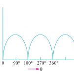
It is also referred to as the bias characteristic of the capacitor and the DC voltage characteristic of the capacitor by some individuals. As seen in the picture below, if a DC voltage is applied to the capacitor’s two ends, the capacitance value will decrease as the DC voltage increases.
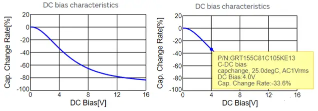
It is a 1uF capacitor in a 0402 package with the designation GRT155C81C105KE13 bias voltage characteristic curve. As the DC voltage increases, the capacitor’s capacity rapidly decreases, as seen in the left image. When the voltage across the capacitor is 4V and the 1uF capacitor has lowered by 33.6 percent to become 1*(1-0.336)=0.664uF, how can the impact of this parameter be comprehended more intuitively? How may bias voltage be removed from practical applications in circuit design?
Illustration – 1st Order RC Low Pass Filter
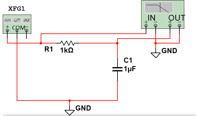
We will use the first-order RC low-pass filter circuit as an illustration to make the introduction more understandable.
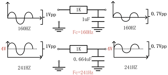
The first-order RC low-pass filter shown below has a resistance of 1K, a capacitor of 1uF, and a cut-off frequency of Fc=1/(2** R*C)=160Hz, meaning that when a sinusoidal signal with a frequency of 160Hz is input at 1Vpp, the output signal will be attenuated by 3dB, the peak-to-peak value will change to 0.7Vpp, the signal with a frequency of 160Hz will be On the second row, the same capacitor and circuitry are still in use. The input signal is the only difference. The input signal is now added with a 4V DC bias. The bias voltage graph above makes it obvious that the capacitor’s capacitance value is falling. It becomes 0.664uF at 33.6 percent, altering the cutoff frequency to 241Hz. The theoretical output frequency is 241Hz@0.7Vpp, while the input signal is a sinusoidal waveform with a frequency of 241Hz@1Vpp.
Actual Practice
Everyone, I know, prefers actual practice than a theoretical introduction. After that, I’ll test the circuit itself. The test setup and process are rather simple. With a 1uF capacitance value, two distinct sorts of studies are carried out. In all tests, a 1Vpp sine signal is loaded at the input end, followed by frequency scanning from 1Hz to 10KHz, waveform collection at the output end, and gain curve design (Bode diagram). This Based on this concept, the network analyzer employs a process called as frequency sweeping. The second test will superimpose a 4V DC signal while test 1’s signal is a pure AC signal. This is the only difference between the two tests.
Outcome for test 1
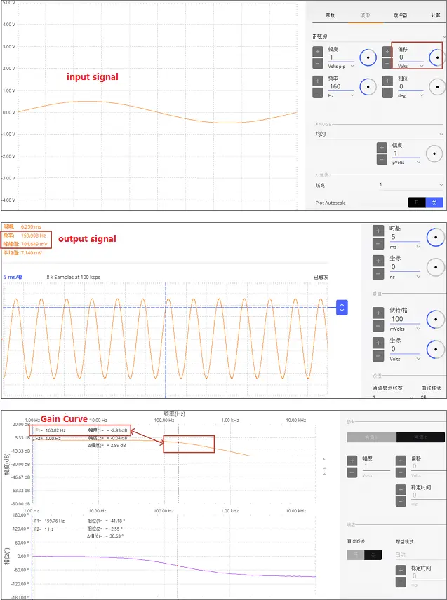
The graphic below displays the test outcome for test 1. Theoretically, based on calculations utilizing the 1K resistor and 1uF capacitor, the cutoff frequency should be 160Hz. The input signal is at 160Hz@1Vpp on the first line, while the output signal is on the second line. The attenuation of 1Vpp is, as can be shown, 0.7Vpp at the cutoff frequency of 160Hz, which is consistent with the earlier theoretical estimate. The third line of the gain curve graph displays a frequency sweep from 1Hz to 10KHz with a -3dB frequency point at 160Hz, which is consistent with the results of the earlier theoretical study.
Outcome for test 2
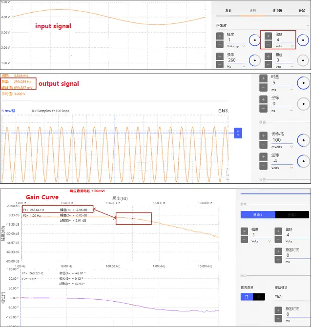
The graphic below displays the test outcome for test 2. The same capacitor and resistor as in test 1 are utilized here. There is 1K of resistance and 1uF of capacitance. The added 4V DC power should theoretically cause the capacitance to fall to 0.664uF. Theoretically, 241Hz should be the cutoff frequency for calculations using capacitors, according to the 1K resistance and 0.664uF. The output signal is on line two, and a 4V DC signal is superimposed on the 260Hz@1Vpp sinusoidal input signal on line one. The attenuation of 1Vpp at the 260Hz cutoff frequency, as can be shown, is 0.7Vpp, which is very comparable to the previous theoretical analysis at 241Hz. The third line of the gain curve graph shows the -3dB frequency point position at 260Hz, which is nearly identical to the 241Hz of the previous theoretical study result. From 1Hz to 10KHz, the scanning frequency is available.
The two tests listed above demonstrate that adding a DC voltage to the input signal would affect the true capacitance value for a given resistance and capacitance. The input signals employed determine the cut-off frequency of the bias voltage band. As a result, the power supply often uses a large number of parallel-connected, large-capacity capacitors. When a signal is amplified, the influence of the bias voltage should be considered and a suitable capacitor should be employed if the signal from the rear stage contains a bias voltage. For positive and negative bipolar bidirectional power supplies, the typical needs are modest; however, for single power supplies, they are larger. Typically, the acquisition circuit’s signal varies according to Vcc/2. This DC voltage must be fully considered in the circuit design.
Note: Conventional circuit simulation software cannot reproduce the bias voltage of the actual capacitor. For instance, no matter how the DC bias voltage varies, 1uF in the simulation program will always be 1uF. It’s important to note that!
For instance, the circuit simulation depicted in the image below still has 1K and 1uF. The simulation can only function because of the 3dB cut-off frequency, which is always 160Hz regardless of how much DC signal is superimposed. The key is the collection of thorough theoretical guiding concepts and real-world application experience.