An amplidyne is an electromechanical amplifier with the characteristics of a rotating machine. It was invented prior to the second world war by Ernst Alexanderson. It is now mostly obsolete.
An amplidyne is a special-purpose DC generator. It comprises an electric motor that turns a generator on the same shaft. It supplies large currents, precisely controlled, to the large motors used to drive heavy physical loads, such as gun turrets and missile launchers.
Amplidyne is used to generate a voltage that proportional to an input current, effectively amplifying the input in scenarios demanding substantial output power.
Amplidynes are now obsolete technology, replaced by modern power semiconductor electronic devices such as MOSFETs and IGBTs which can produce output power in the kilowatt range.
Comparing the working principle an amplidyne is closely related to the Rosenberg generator and the metadyne. Although they are used for different purposes.
- Rosenberg generator is a constant-current source of dc electric power.
- Metadyne in its usual form is a machine for converting constant potential dc energy into constant current dc energy
- Amplidyne generator is a dynamoelectric amplifier.
Amplidyne is the most common version of the Metadyne. It consists of the basic metadyne in which a compensating winding is connected in series with the power output brush terminals.
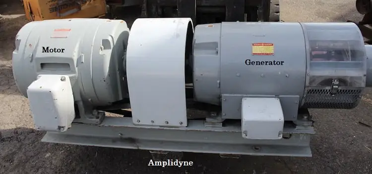
The amplidyne consists of a motor and a generator. It consists of a constant-speed AC motor (the prime mover) mechanically coupled to a DC generator. The generator is wired to function as a high-gain amplifier (an amplifier is a device in which a small input voltage can control a large current source).
For instance, in a normal DC generator, a small DC voltage applied to the field windings is able to control the output of the generator.
In a typical generator, a change in voltage from 0 volt to 3 volts DC applied to the field winding may cause the generator output to vary from 0 volt to 300 volts DC. If the 3 volts applied to the field winding is considered an input, and the 300 volts taken from the brushes is output, there is a gain of 100.
Gain is expressed as the ratio of output to input:
Gain = Output / Input
In this case, Gain = 300 V ÷ 3 V = 100
This means that the 3 volts output is 100 times larger than the input.
The remaining article will explain how gain is achieved in a typical DC generator and how the modifications making the generator an amplidyne increase the gain to as high as 10,000.
Working of Amplidyne
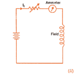
We will explain the working of amplidyne through the modification of a separately excited dc generator to amplidyne. The figure below shows the schematic diagram of a separately excited DC generator.
Because of the 10-volt controlling voltage, 10 amperes of current will flow through the ohm field winding. This draws 100 watts of input power (P = V*I).
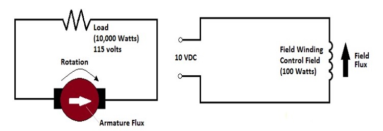
Assume that the characteristics of this generator enable it to produce approximately 87 amperes of armature current at 115 volts at the output terminals. This represents an output power of approximately 10,000 watts (P = V*I). You can see that the power gain of this generator is 100.
In effect, 100 watts controls 10,000 watts.
An amplidyne is a special type of DC generator. The following changes, for explanation purposes, will convert the typical DC generator above into an amplidyne.
The first step is to short the brushes together, as shown in figure below. This removes nearly all of the resistance in the armature circuit.

Because of the very low resistance in the armature circuit, a much lower control-field flux produces full-load armature current (full-load current in the armature is still about 87 amperes).
The smaller control field now requires a control voltage of only 1 volt and an input power of 1 watt (1 volt across 1 ohm causes 1 ampere of current, which produces 1 watt of input power).
The next step is to add another set of brushes. These now become the output brushes of the amplidyne. They are placed against the commutator in a position perpendicular to the original brushes, as shown in the figure below.
The previously shorted brushes are now called the “quadrature” brushes. This is because they are in quadrature (perpendicular) to the output brushes. The output brushes are in line with the armature flux. Therefore, they pick off the voltage induced in the armature windings at this point. The voltage at the output will be the same as in the original generator, 115 volts in our example.

As you have seen, the original generator produced a 10,000-watt output with a 100-watt input.
The amplidyne produces the same 10,000-watt output with only a one-watt input. This represents a gain of 10,000. The gain of the original generator has been greatly increased.
As previously stated, an amplidyne is used to provide large DC currents. The primary use of an amplidyne is in the positioning of heavy loads through the use of synchro/servo systems.
Application of Amplidyne
Basically, the amplidyne can be utilized as a voltage regulator, a current regulator, or as a speed regulator.

As previously stated, an amplidyne is used to provide large DC currents. The primary use of an amplidyne is in the positioning of heavy loads through the use of synchro/servo systems.
The amplidyne was first used in the US Navy in servo systems to control the electric motors rotating naval gun mounts, to aim the gun at a target.
Assume that a very large turning force is required to rotate a heavy object, such as an antenna, to a very precise position. A low-power, relatively weak voltage representing the amount of antenna rotation required can be used to control the field winding of an amplidyne.
Because of the amplidyne’s ability to amplify, its output can be used to drive a powerful motor, which turns the heavy object (antenna). When the source of the input voltage senses the correct movement of the object, it drops the voltage to zero. The field is no longer strong enough to allow an output voltage to be developed, so the motor ceases to drive the object (antenna).
The above is an oversimplification and is not meant to describe a functioning system. The intent is to show a typical sequence of events between the demand for movement and the movement itself.
It is meant to strengthen the idea that with the amplidyne, something large and heavy can be controlled very precisely by something very small, almost insignificant.


Comments are closed.