DC generators are widely used in various applications such as electric vehicles, renewable energy systems, and industrial machinery. Among the different types of DC generators, separately excited DC generators are the most commonly used ones. In this article, we will explore the basics of separately excited DC generators, their working principles, applications, and advantages.
What is a Separately Excited DC Generator?
A separately excited DC generator is a type of DC generator that uses a separate external source of field current to excite the magnetic field of the generator. This external source can be a battery, a DC power supply, a controlled rectifier, a diode rectifier or another DC generator.
The steady-state model of the separately excited dc generator is shown in figure below.
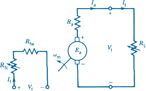
In this model
Rfw is the resistance of the field winding.
Rfc is the resistance of the control rheostat used in the field circuit.
Rf =Rfw +Rfc is the total field circuit resistance.
Ra is the resistance of the armature circuit, including the effects of the brushes.
RL is the resistance of the load.
Sometimes Ra is shown as the resistance of the armature winding alone; the brush–contact voltage drop is considered separately and is usually assumed to be about 2 V.
In the steady-state model, the inductances of the field winding and armature winding are not considered.
The defining equations are the following:
Vf =RfIf
Ea =Vt +IaRa
Ea =KaΦωm
Vt =ItRL
Ia =It
Vt =Ea – RaIa
This equation defines the terminal or external characteristic of the separately excited dc generator
Characteristics of Separately excited dc Generator
The characteristic of seperately excited dc generator is shown in the figure below.
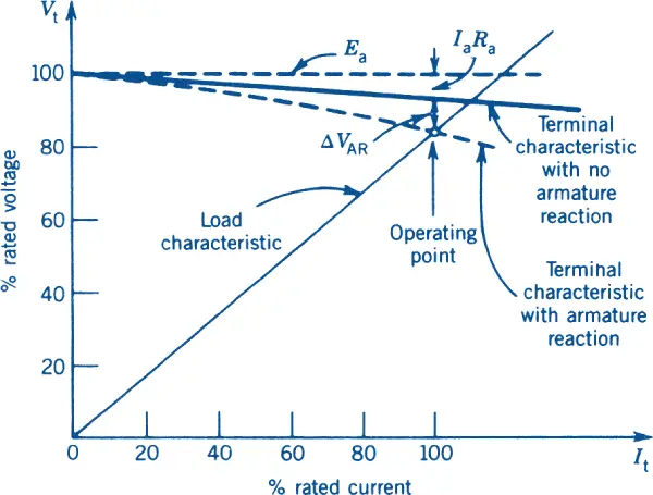
As the terminal (i.e., load) current It increases, the terminal voltage Vt decreases linearly (assuming Ea remains constant) because of the voltage drop across Ra. This voltage drop IaRa is small, because the resistance of the armature circuit Ra is small. A separately excited dc generator maintains an essentially constant terminal voltage.
At high values of the armature current a further voltage drop (ΔVAR) occurs in the terminal voltage; that is known as armature reaction (or the demagnetization effect) and causes a divergence from the linear relationship. This effect can be neglected for armature currents below the rated current.
The load characteristic, defined by equation Vt =Ea – RaIa, is also shown in figure above. The point of intersection between the generator external characteristic and the load characteristic determines the operating point—that is, the operating values of the terminal voltage Vt and the terminal current It.
Working Principle of Separately Excited DC Generator
The working principle of a separately excited DC generator can be further understood by examining the relationship between terminal current (It), terminal voltage (Vt), and the external characteristic of the generator.
As the terminal current increases, the terminal voltage decreases linearly (assuming Ea remains constant) due to the voltage drop across the armature resistance (Ra). The voltage drop IaRa is relatively small because the resistance of the armature circuit is low. This characteristic allows a separately excited DC generator to maintain an essentially constant terminal voltage.
However, at high values of the armature current, an additional voltage drop (ΔVAR) occurs in the terminal voltage. This phenomenon is known as armature reaction or the demagnetization effect. It causes a deviation from the linear relationship between terminal current and voltage. For armature currents below the rated current, this effect can be neglected.
To better visualize the relationship between terminal voltage and current, the load characteristic is defined by the equation Vt = Ea – RaIa. The load characteristic curve shows how the terminal voltage varies with changes in the terminal current. The point of intersection between the generator’s external characteristic curve and the load characteristic curve determines the operating point. In other words, it determines the specific values of terminal voltage (Vt) and terminal current (It) at a given operating condition.
By understanding the interplay between terminal current, terminal voltage, and the load characteristic, engineers can effectively analyze and control the performance of a separately excited DC generator. This knowledge enables them to optimize the generator’s operation within desired voltage and current limits.
Components of Separately Excited DC Generator
Now that we have explored the working principle of a separately excited DC generator, let’s delve into its key components. Understanding these construction of dc machine will provide a clearer picture of how the generator operates.
- Armature: The armature is the rotating part of the generator and consists of a set of conductive coils or windings. When the armature rotates within the magnetic field, it generates the electrical output.
- Field Winding: The field winding is the stationary part of the generator responsible for producing the magnetic field. In a separately excited DC generator, the field winding is connected to an external source of field current. This current creates the magnetic field required for the generation of electricity.
- Commutator: The commutator is a mechanical device mounted on the armature shaft. Its function is to convert the alternating current (AC) output of the armature into direct current (DC) output. It achieves this conversion by periodically reversing the current direction in the armature windings, ensuring a unidirectional flow of current in the external circuit.
- Brushes: The brushes are stationary conductive elements that make contact with the commutator segments. They are responsible for transferring the electrical output from the armature to the external load or circuit. Brushes are typically made of carbon or carbon-graphite materials, which offer good conductivity and wear resistance.
These components work together to enable the operation of a separately excited DC generator. The armature windings produce the electrical output, while the field winding creates the necessary magnetic field. The commutator and brushes ensure the conversion and transfer of the generated electricity to the external load.
Understanding the role of each component is essential for troubleshooting and maintaining a separately excited DC generator. It allows engineers to identify potential issues and implement appropriate measures to ensure optimal performance.
Applications and Advantages
Separately excited DC generators are widely used in various applications such as:
- Battery charging systems
- Electric vehicles
- Industrial machinery
- Renewable energy systems
- DC power supplies
- Aerospace and defense systems
The advantages of using a separately excited DC generator are:
- Better voltage regulation
- Higher efficiency
- Improved reliability
- Better control over the output voltage
- Ability to operate at variable speeds