• Home
  • Courses
  • Machines
    • Transformer
    • AC Motors
      • Induction Motor
      • Synchronous Motor
    • DC Motor
    • DC Generator
  • Power System
    • Circuit Breaker
    • Switchgear
    • Substation
    • Control System
    • Measurement
  • Electronics
  • Blog
  • Contact
    • Contact Us
    • Privacy Policy
Have any question?
[email protected]
Login
StudyElectrical.Com
  • Home
  • Courses
  • Machines
    • Transformer
    • AC Motors
      • Induction Motor
      • Synchronous Motor
    • DC Motor
    • DC Generator
  • Power System
    • Circuit Breaker
    • Switchgear
    • Substation
    • Control System
    • Measurement
  • Electronics
  • Blog
  • Contact
    • Contact Us
    • Privacy Policy

    Power System

    Why Current Transformer (CT) Seconday Should not be Open ?

    • Categories Power System, Electrical Machines, Transformer
    Why 2BCT 2Bsecondary 2Bshould 2Bnot 2Bopen
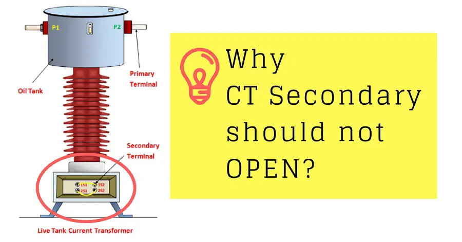
    Amazed why secondary of current transformer should not be open? If it is left open it may destroy the current transformer.
    So it is very important that the secondary of Current Transformer should not be kept open.  The reason is quite interesting.

    Either it should be shorted or must be connected in series with a low resistance coil such as current coils of watt meter, coil of ammeter etc.

    Related: Why Transformers are Rated in kVA, Not in kW?

    If it is left open, then current through secondary becomes zero hence the ampere turns produced by secondary which generally oppose primary ampere turns becomes zero. 

    As there is no counter m.m.f., unopposed primary m.m.f. (ampere turns) produce high flux in the core. 

    • This produce excessive core losses, heating the core beyond limits. 
    • Similarly heavy e.m.f.s will be induced on the primary and secondary side. This may damage the insulation of the winding. 

    This is danger from the operator point of view as well. It is usual to ground the C.T. on the secondary side to avoid a danger of shock to the operator. 

    Hence never open the secondary winding circuit of a current transformer while its primary winding is energized. 

    Thus most of the current transformers have a short circuit link or a switch at secondary terminals. When the primary is to be energized, the short circuit link must be closed so that there is no danger of open circuit secondary. 
    Related Articles

    • Practical 2Btransformer 2Bon 2Bno 2Bload
      Practical Transformer on No Load

      Please read Ideal Transformer and Practical Transformer before continuing. Consider a practical transformer on no load…

    • ideal 2Btransformer 2Bphasor 2Bdiagram
      Ideal Transformer and Practical Transformer

      Ideal Transformer An ideal transformer is one that has no winding resistance no leakage flux…

    • Rectifier Transformers
      Rectifier Transformer - Working Principle and Application

      What is the Rectifier Transformer? Rectifier transformers are different from normal power and distribution transformers…

    • Construction of High Voltage Current Transformer
      Basic Types of Current Transformers

      Current Transformers (CT’s) are instrument transformers that are used to supply a reduced value of…

    • Effects of Voltage and Frequency Variation on Transformers
      Why Transformer does not work on DC supply?

      Did you ever think about what will happen to a transformer on dc supply? In…

    • Current 2BTransformer 2BConstruction 2Bor 2BCircuit 2BDiagram 2Band 2BSymbol
      Current Transformer (CT) - Construction and Working Principle

      A current transformer (CT) is a type of transformer that is used to measure AC…

    • Share:
    author avatar
    Electrical Engineer

    Previous post

    Ideal Transformer and Practical Transformer
    June 10, 2018

    Next post

    What Jobs Electrical Engineers Do? | Roles and Responsibilities
    July 11, 2018

    You may also like

    EICR Guide
    What is an EICR: Essential Guide to Electrical Installation Condition Reports
    17 May, 2023
    Equivalent Circuit for Tan δ Measurement and Phasor Diagram
    Tan Delta Test | Loss Angle Test | Dissipation Factor Test
    9 May, 2023
    separately excited dc generator characteristics
    Beginner’s Guide to Separately Excited DC Generator
    8 May, 2023

    Leave A Reply Cancel reply

    Your email address will not be published. Required fields are marked *

    Search Here

    From Blog

    Objective Questions on Electric Traction – 1
    21May2014
    Thin film application iin electronics
    The Various Applications Of Thin Films In Electronics And Other Equipment
    16Jan2023
    Insulation Resistance Tester Megger
    Insulation Resistance Test (IR Test) or Megger Test
    16Aug2014
    types of dc generator
    Types of DC Generator – Series, Shunt and Compound
    06Aug2014

    Categories

    • Alternator
    • Arduino
    • Basic Electrical
    • Battery
    • Books
    • Cables
    • Capacitor
    • Career
    • Circuit Breaker
    • Control System
    • DC Generator
    • DC Generator MCQ
    • DC Generator Solved Problems
    • DC Motor
    • DC Motor MCQ
    • Drives
    • Electric Vehicles
    • Electrical Circuits
    • Electrical Machines
    • Electrical Relays
    • Electrical Safety
    • Electronics
    • Embedded System
    • Exams
    • Generation
    • Guest Post
    • HVDC
    • Instrumentation
    • Interview Questions
    • Locomotives
    • MCQ
    • Measurement
    • Microcontroller
    • Objective Questions
    • PCB
    • PLC
    • Power System
    • Problems and Solution
    • Projects
    • Resistor
    • Signals and Systems
    • Single Phase Motors
    • Substation
    • Switchgear
    • Synchronous Motor
    • Three Phase Induction Motor
    • Transformer
    • Transmission Line
    • Uncategorized

    Copyright © 2021 Study Electrical, Inc.

    © StudyElectrical.Com 2021

    Login with your site account

    Lost your password?

    x
    x