A voltmeter is an instrument used for measuring electrical potential difference between two points in an electric circuit. Analog voltmeters move a pointer across a scale in proportion to the voltage of the circuit; digital voltmeters give a numerical display of voltage by use of an analog to digital converter.
We are using internal ADC of Arduino to make Digital Voltmeter capable to display 0 to 5V. You can increase its input voltage capacity by using voltage divider circuit.
What you will learn?
1. How to connect 7-Segment Display to Arduino?
2. How to read analog input?
3. Use of shift register to reduce IOs.
4. Measurement of DC voltage using Arduino.
Components Required
1. Arduino Uno
2. 4 digit 7-segment Display Common Cathode.
3. Variable Resistor.
4. 1K Resistors
5. 75HC595
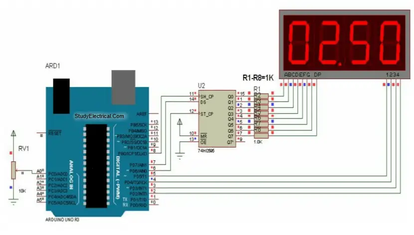
Digital Voltmeter Circuit
Main components of object counter circuit are
- 4 digit 7 segment display,
- Arduino Uno,
- 74HC595

Digital Voltmeter Arduino Code
The program is constructed using “TimerOne” library. Program have different modules, Setup, Loop.
In setup we initialize all the IO connections and Timer, Display.
In main loop we are taking Analog input and constantly updating display to show voltage value.
#include <TimerOne.h>
//Define 74HC595 Connections with arduio
const int Data =7;
const int Clock=8;
const int Latch=6;
const int SEG0 =5;
const int SEG1 =4;
const int SEG2 =3;
const int SEG3 =2;
int cc =0;
char Value [4];
const char SegData []={0x3F,0x06,0x5B,0x4F,0x66,0x6D,0x7D,0x07,0x7F,0x6F};
//=============================================================
// Setup
//=============================================================
void setup () {
// initialize the digital pin as an output.
Serial . begin(9600);
pinMode ( Data , OUTPUT );
pinMode ( Clock, OUTPUT );
pinMode ( Latch, OUTPUT );
pinMode ( SEG0 , OUTPUT );
pinMode ( SEG1 , OUTPUT );
pinMode ( SEG2 , OUTPUT );
pinMode ( SEG3 , OUTPUT );
//Initialize Display Scanner
cc =0;
Timer1 . initialize (10000); // set a timer of length 100000 microseconds (or 0.1 sec – or 10Hz
=> the led will blink 5 times, 5 cycles of on-and-off, per second)
Timer1 . attachInterrupt ( timerIsr ); // attach the service routine here
}
//=============================================================
// Loop
//=============================================================
void loop () {
char Volt [4];
int Voltage = analogRead ( A0 );
//To get fixed point decimal point we multiply it by 100
Voltage = (500/1024.0) * Voltage ; //Scaling of 0 to 5V i.e. 0 to 1023 to 0 to 10 (in 10 steps)
//Display Voltage on Segments
sprintf ( Volt ,”%04d”, Voltage ); //We get ASCII array in Volt
Serial . println( Volt );
Value [0]= Volt [0] & 0x0F; //Anding with 0x0F to remove upper nibble
Value [1]= Volt [1] & 0x0F; //Ex. number 2 in ASCII is 0x32 we want only 2
Value [2]= Volt [2] & 0x0F;
Value [3]= Volt [3] & 0x0F;
delay(200);
}
//=============================================================
// Generates Bargraph
//=============================================================
void DisplayDigit (char d )
{
int i ;
for( i =0; i <8; i ++) //Shift bit by bit data in shift register
{
if(( d & 0x80)==0x80)
{
digitalWrite ( Data , HIGH );
}
else
{
digitalWrite ( Data , LOW );
}
d = d <<1;
//Give Clock pulse
digitalWrite ( Clock, LOW );
digitalWrite ( Clock, HIGH );
}
//Latch the data
digitalWrite ( Latch, LOW );
digitalWrite ( Latch, HIGH );
}
//===================================================================
// TIMER 1 OVERFLOW INTTERRUPT FOR DISPALY
//===================================================================
void timerIsr ()
{
cc ++;
if( cc ==5) //We have only 4 digits
{ cc =1;}
Scanner ();
TCNT0 =0xCC;
}
//===================================================================
// SCAN DISPLAY FUNCTION
//===================================================================
void Scanner ()
{
switch ( cc ) //Depending on which digit is selcted give output
{
case 1:
digitalWrite ( SEG3 , HIGH );
DisplayDigit ( SegData [ Value [0]]);
digitalWrite ( SEG0 , LOW );
break;
case 2:
digitalWrite ( SEG0 , HIGH );
DisplayDigit ( SegData [ Value [1]] | 0x80); //0x80 to turn on decimal point
digitalWrite ( SEG1 , LOW );
break;
case 3:
digitalWrite ( SEG1 , HIGH );
DisplayDigit ( SegData [ Value [2]]);
digitalWrite ( SEG2 , LOW );
break;
case 4:
digitalWrite ( SEG2 , HIGH );
DisplayDigit ( SegData [ Value [3]]);
digitalWrite ( SEG3 , LOW );
break;
}
}
//===================================================================