The difference in level between points of supports and the lowest point on the conductor is called sag in overhead transmission lines.

Sag in transmission lines on Hot and Cold Day
While erecting an overhead line, it is very important that conductors are under safe tension. If the conductors are too much stretched between supports in a bid to save conductor material, the stress in the conductor may reach unsafe value and in certain cases, the conductor may break due to excessive tension.
In order to permit safe tension in the conductors, they are not fully stretched but are allowed to have a dip or sag.
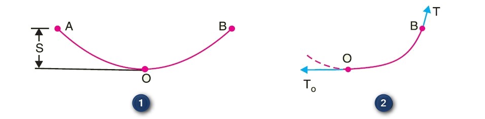
Figure 1 shows a conductor suspended between two equal levels supports A and B. The conductor is not fully stretched but is allowed to have a dip. The lowest point on the conductor is O and the sag is S. The following points may be noted :
- When the conductor is suspended between two supports at the same level, it takes the shape of catenary. However, if the sag is very small compared with the span, then the sag-span curve is like a parabola.
- The tension at any point on the conductor acts tangentially. Thus tension To at the lowest point O acts horizontally as shown in figure 2.
- The horizontal component of tension is constant throughout the length of the wire.
- The tension at supports is approximately equal to the horizontal tension acting at any point on the wire. Thus if T is the tension at the support B, then T = To.
Conductor Sag and Tension
Conductor sag and tension are an important consideration in the mechanical design of overhead lines.
The conductor sag should be kept to a minimum in order to reduce the conductor material required and to avoid extra pole height for sufficient clearance above ground level. It is also desirable that tension in the conductor should be low to avoid the mechanical failure of the conductor and to permit the use of less strong supports.
However, low conductor tension and minimum sag are not possible. It is because low sag means a tight wire and high tension, whereas a low tension means a loose wire and increased sag. Therefore, in actual practice, a compromise is made between the two.
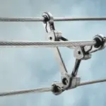
Steel core strands have been used to increase the tensile strength and reduce thermal sag of bare overhead conductors to accommodate longer spans between fewer or shorter structures.
Calculation of Sag
In an overhead line, the sag should be adjusted to maintain safe tension in the conductors. Tension is influenced by conductor weight, wind, ice loading, and temperature fluctuations. Typically, conductor tension is kept below 50% of its ultimate tensile strength to ensure a minimum factor of safety.
We will now determine the sag and tension of a conductor in two scenarios:
- when supports are at the same level and
- when supports are at different levels.
Sag Calculation When Supports are at Same Level
Consider a conductor between two equilevel supports A and B, with O as the lowest point. It can be demonstrated that the lowest point occurs at the mid-span of the conductor between equilevel supports A and B, with O as the lowest point.
Let l be the length of the span, w be the weight per unit length of the conductor, and T be the tension in the conductor.
Consider point P on the conductor with coordinates x and y, where the lowest point O is the origin. Assuming a small curvature where the curved length equals its horizontal projection (OP = x), the forces acting on the portion OP are the weight wx of the conductor at a distance x/2 from O and the tension T acting at O. Equating the moments of these forces about point O gives the maximum dip represented by the value of y at supports A and B. In scenarios where supports are at different levels, as in hilly areas, with a conductor suspended between supports A and B at varying heights, the formulas for sag are derived. The formulae for sag are valid in still air and normal temperature conditions when the conductor is solely affected by its weight. However, in practical situations, the conductor may have ice coating and encounter wind pressure, resulting in a vector sum of horizontal and vertical forces on the conductor. When the conductor faces wind and ice loading, it aligns itself at an angle θ to the vertical, with sag in the conductor given by S = wt*l^2 / 2T, representing the slant sag in a direction at an angle θ to the vertical. If not specified, the vertical sag is calculated as S cos θ.

Comments are closed.