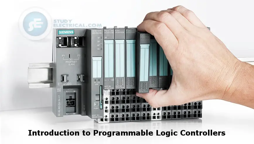
What is a Programmable Logic Controller (PLC)?
A programmable logic controller, PLC, or programmable controller is a user-friendly, microprocessor based specialized computer that carries out control functions of many types and levels of complexity. Its purpose is to monitor crucial process parameters and adjust process operations accordingly.
A PLC is a digital computer used for automation of typically industrial electromechanical processes, such as control of machinery on factory assembly lines, amusement rides, or light fixtures. PLCs are used in many machines, in many industries.
PLC are used extensively because
- Is easy to set up and program.
- Behaves predictably, ruggedized.
- It can be programmed (to a degree), controlled, and operated by a person unskilled in operating (programming) computers.
Essentially, a PLC’s operator draws the lines and devices of ladder diagrams with a keyboard/mouse onto a display screen. The resulting ladder diagram is converted into computer machine language and run as a program.
The PLC has input lines where sensors are connected to notify upon events (e.g. temperature above/below a certain level, liquid level reached, etc.), and output lines to signal any reaction to the incoming events (e.g. start an engine, open/close a valve, etc.).
Function of PLC
A PLC is primarily used to control machinery. Programs written for PLCs consists in simple terms on instructions to turn on and off outputs based on input conditions and the internal program. In this aspect, it is similar to a computer. However, one designed to be programmed once, and run repeatedly as needed. In fact, a crafty programmer could use a PLC to control not only simple devices such as a garage door opener, but their whole house, including switching lights on and off at certain times, monitoring a custom built security system, etc.
Most commonly, a PLC is found inside of a machine in an industrial environment. A PLC can run an automatic machine for years with little human intervention. They are designed to withstand most harsh environments.
PLC Examples
Allen-Bradley PLC5
Allen-Bradley SLC500
Allen-Bradley Micrologix
Allen-Bradley Picocontroller
PLC basics
Some PLCs are integrated into a single unit (Picocontroller), whereas others are modular (PLC5, SLC500). The Micrologix product lies somewhere between the PLC5 and the Picocontroller
Integrated PLCs are sometimes called brick PLCs because of their small size.These PLCs have embedded I/O (i.e. the I/O is apart of the same unit as the controller itself).
Modular PLCs have extended I/O
Components in a PLC system
 CPU module, containing the processor and memory. Input and output modules, to allow the PLC to read sensors and control actuators. A wide variety of types are available.
Power supply for the PLC, and often sensors and low power actuators connected to I/O modules. A rack or bus so the PLC can exchange data with I/O modules
A programming unit is necessary to create, edit and download a user program to the PLC.
Additional components can include:
- Network interfaces: to allow PLCs to function in a networked environment
- Communication adapters for remote I/O devices: so I/O devices do not have to be physically close to the CPU module
- Operator interface devices: allow monitoring and/or data entry by operators
Definition And History Of The PLC
The PLC takes the place of much of the external wiring required for control of a process. The PLC will operate any system that has output devices that go on and off (known as discrete, or digital, outputs). It can also operate any system with variable (analog) outputs.
The PLC can be operated on the input side by on-off devices (discrete, or digital) or by variable (analog) input devices. The first PLC systems evolved from conventional computers in the late 1960s and early 1970s. These first PLCs were installed primarily in automotive plants.
Traditionally, the auto plants had to be shut down for up to a month at model changeover time. The early PLCs were used along with other new automation techniques to shorten the changeover time. One of the major time-consuming changeover procedures had been the wiring of new or revised relay and control panels.
The PLC keyboard reprogramming procedure replaced the rewiring of a panel full of wires, relays, timers, and other components. The new PLCs helped reduce changeover time to a matter of a few days.
PLC Advantages
Flexibility
In the past, each different electronically controlled production machine required its own controller; 15 machines might require 15 different controllers. Now it is possible to use just one model of a PLC to run any one of the 15 machines.
Furthermore, you would probably need fewer than 15 controllers, because one PLC can easily runmany machines.
Each of the 15 machines under PLC control would have its own distinct program (or a portion of one running program).
Implementing Changes and Correcting Errors
With a wired relay-type panel, any program alterations require time for rewiring of panels anddevices.When a PLC program circuit or sequence design change is made, the PLC program can be changedfrom a keyboard sequence in a matter of minutes.
– No rewiring is required for a PLC-controlled system.
– Also, if a programming error has to be corrected in a PLC control ladder diagram, a change can betyped in quickly.
Large Quantities of Contacts
The PLC has a large number of contacts for each coil available in its programming. Suppose that a panel-wired relay has four contacts and all are in use when a design change requiring three more contacts is made.
Time would have to be taken to procure and install a new relay or relay contact block. Using a PLC, however, only three more contacts would be typed in. Contacts are now a “software” component .
Lower Cost
Increased technology makes it possible to condense more functions into smaller and less
expensive packages. Now you can purchase a PLC with numerous relays, timers, and counters, a sequencer, and other functions for a few hundred dollars.
Pilot Running
A PLC programmed circuit can be evaluated in the lab. The program can be typed in, tested,
observed, and modified if needed, saving valuable factory time.
Visual Observation
A PLC circuit’s operation can be seen during operation directly on a CRT screen. The operation or mis-operation of a circuit can be observed as it happens.
Logic paths light up on the screen as they are energized. Troubleshooting can be done more quickly during visual observation.
Ladder or Boolean Programming Method
The PLC programming can be accomplished in the ladder mode by an engineer, electrician or possibly a technician. Alternatively, a PLC programmer who works in digital or Boolean
control systems can also easily perform PLC programming.
Reliability and Maintainability
Solid-state devices are more reliable, in general, than mechanical systems or relays and timers. Consequently, the control system maintenance costs are low and downtime is minimal.
Documentation
An immediate printout of the true PLC circuit is available in minutes, if required. There is no need to look for the blueprint of the circuit in remote files. The PLC prints out the actual circuit in operation at a given moment.
Often, the file prints for relay panels are not properly kept up to date. A PLC printout is the circuit at the present time; no wire tracing is needed for verification.
PLC Disadvantages
Fixed Program Applications
Some applications are single-function applications. It does not pay to use a PLC that includes multiple programming capabilities if they are not needed. Their operational sequence is seldom or never changed, so the reprogramming available with the PLC would not be necessary.
Fail-Safe Operation
In relay systems, the stop button electrically disconnects the circuit; if the power fails, the system stops. This, of course, can be programmed into the PLC; however, in some PLC programs, you may have to apply an input voltage to cause a device to stop. These systems may not be fail-safe.