• Home
  • Courses
  • Machines
    • Transformer
    • AC Motors
      • Induction Motor
      • Synchronous Motor
    • DC Motor
    • DC Generator
  • Power System
    • Circuit Breaker
    • Switchgear
    • Substation
    • Control System
    • Measurement
  • Electronics
  • Blog
  • Contact
    • Contact Us
    • Privacy Policy
Have any question?
[email protected]
RegisterLogin
StudyElectrical.Com
  • Home
  • Courses
  • Machines
    • Transformer
    • AC Motors
      • Induction Motor
      • Synchronous Motor
    • DC Motor
    • DC Generator
  • Power System
    • Circuit Breaker
    • Switchgear
    • Substation
    • Control System
    • Measurement
  • Electronics
  • Blog
  • Contact
    • Contact Us
    • Privacy Policy

PLC

The Basics of Programmable Logic Controller (PLC) that You Never Learned

  • Categories PLC
Programmable Logic Controllers

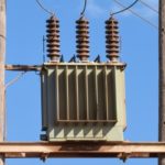
Programmable Logic Controllers (PLCs) are also referred to as programmable controllers in some places. They are widely used in commercial and industrial applications.

Basically, a PLC monitors inputs, makes decisions based on its program, and controls outputs to automate a process or machine. This article will give you basic information on the basic functions and configurations of PLCs.

Actual PLC
An actual PLC will look like this

Table of Contents

  • Basic PLC Working
    • Example of PLC Application
    • Hard-Wired Control
  • Advantages of PLCs
    • Related Articles

Basic PLC Working

A programmable logic controller (PLC) consist of the following parts

  1. Input modules or points
  2. Central Processing Unit (CPU)
  3. Output modules or points.
  4. Programming device
  5. Operator Interface device
plc parts
plc parts

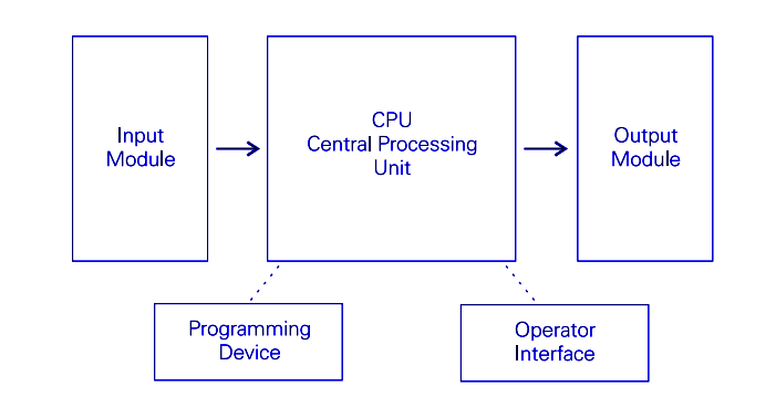
An input module accepts a variety of digital or analog signals from various field devices (sensors) and converts them into a logic signal. This logic signal can be used by the CPU.

The CPU makes decisions and executes control instructions. It is completely based on program instructions in memory.

Output modules are used to convert control instructions from the CPU into a digital or analog signal. This signal can be used to control various field devices (actuators).

A programming device is used to input the desired instructions to the PLC. These instructions given to the PLC determine what the PLC will do for a specific input.

An operator interface device is also used. This allows process information to be displayed and new control parameters to be entered.

Example of PLC Application

In this example a PLC is used to start and stop a motor. Pushbuttons are used as sensors are connected to the PLC inputs. A motor starter is connected to the output of the PLC.

Plc application start stop motor
PLC application start stop motor

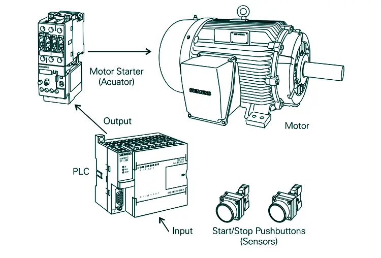
The pushbuttons can be used to start and stop a motor connected to a PLC through a motor starter (actuator).

Hard-Wired Control

Before the invention of PLCs, many of these control tasks were solved with contactor or relay controls. This is often referred to as hardwired control.

hardwired control
hardwired control

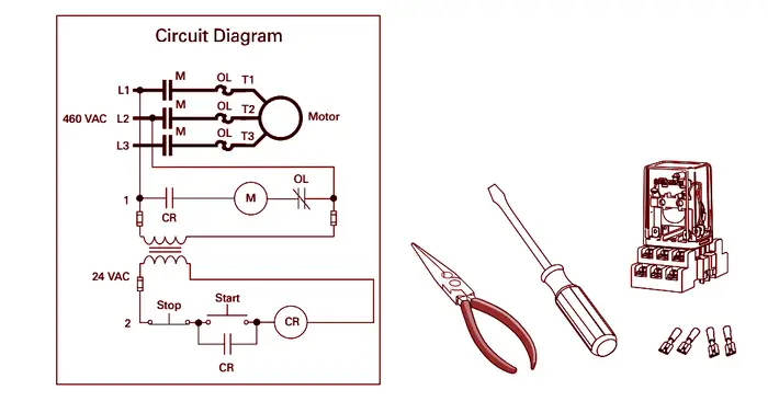
In hard wired control circuit diagrams had to be designed, electrical components specified and installed, and wiring lists created. Electricians wire the components necessary to perform a specific task.

If an error was made the wires had to be reconnected correctly. A change in function or system expansion required extensive component changes and rewiring.

Advantages of PLCs

The same, as well as more complex tasks, can be done with a PLC. Wiring between devices and relay contacts is done in the PLC program. Hard-wiring, though still required to connect field devices, is less intensive.

Modifying the application and correcting errors are easier to handle. It is easier to create and change a program in a PLC than it is to wire and rewire a circuit.

Following are just a few of the advantages of PLCs:

  • Smaller physical size than hard-wire solutions.
  • Easier and faster to make changes.
  • PLCs have integrated diagnostics and override functions.
  • Diagnostics are centrally available.
  • Applications can be immediately documented.
  • Applications can be duplicated faster and less expensively

Related Articles

  • Three Phase Transformer
    Three-Phase Transformer - Basics and Connection Methods

    Three-phase transformers are used in three-phase circuits to step up and step down the voltage…

  • Substation Relay
    Basics of Protective Relaying in Power System

    Protective relaying is necessary with almost every electrical plant, and no part of the power…

  • Automatic Light Controller arduino
    Arduino based Automatic Light Controller

    The automatic light controller offers energy saving and convenience in the areas with a photosensor…

  • plc 2
    Introduction to PLC Ladder Programming

    We have already discussed the introduction to programmable logic controllers. Please go through it before…

  • Programmable%2Blogic%2Bcontroller%2BPLC%2BLectures%2BNotes
    14 Lectures on Programmable Logic Controllers (PLC)

    A PLC is a user-friendly, microprocessor based specialized computer that carries out control functions of…

  • introduction to programmable logic controller
    Introduction to Programmable Logic Controllers (PLCs)

    What is a Programmable Logic Controller (PLC)? A programmable logic controller, PLC, or programmable controller is a…

  • Share:
Tesla Edison
Tesla Edison

Tesla is an Electrical Engineer, Physicist and an Inventor in making. He is a good writer and author of many courses and articles published in this site.

Previous post

Beginner Friendly Kits That Most Newbie Used In Electronics
March 28, 2020

Next post

Fundamentals of Electric Circuits
April 6, 2020

You may also like

ladder diagram
What is Ladder Diagram and How to Draw a Ladder Diagram?
21 August, 2017
plc_2
Introduction to PLC Ladder Programming
2 August, 2017
introduction to programmable logic controller
Introduction to Programmable Logic Controllers (PLCs)
9 October, 2015

Leave A Reply Cancel reply

Your email address will not be published. Required fields are marked *

Search Here

From Blog

digital lock arduino
How to Make a Digital Lock Using Arduino?
01Nov2016
star star transformer
Star-Star (Y-Y) Connection of Three Phase Transformers
05Nov2014
newbie electronics kits
Beginner Friendly Kits That Most Newbie Used In Electronics
16Mar2020
what is fuse
What is a FUSE and How it Works?
23Sep2017

Categories

  • Alternator
  • Arduino
  • Basic Electrical
  • Battery
  • Books
  • Cables
  • Capacitor
  • Career
  • Circuit Breaker
  • Control System
  • DC Generator
  • DC Motor
  • Electric Vehicles
  • Electrical Circuits
  • Electrical Machines
  • Electrical Relays
  • Electrical Safety
  • Electronics
  • Embedded System
  • Exams
  • Generation
  • Guest Post
  • HVDC
  • Instrumentation
  • Interview Questions
  • Locomotives
  • Measurement
  • Microcontroller
  • Objective Questions
  • PCB
  • PLC
  • Power System
  • Projects
  • Signals and Systems
  • Single Phase Motors
  • Substation
  • Switchgear
  • Synchronous Motor
  • Three Phase Induction Motor
  • Transformer
  • Transmission Line
  • Uncategorized

Copyright © 2021 Study Electrical, Inc.

© StudyElectrical.Com 2021

Login with your site account

Lost your password?

Not a member yet? Register now

Register a new account

Are you a member? Login now