A transformer is a fundamental electrical device that transfers electrical energy between two or more circuits through the principle of electromagnetic induction. It is widely used in power systems to increase or decrease voltage levels while ideally maintaining constant power. This enables efficient long-distance transmission and safe utilization of electrical energy.
Introduction to Transformers
Transformers are static devices — they contain no moving parts — and operate only on alternating current (AC). Their main function is to step up or step down voltage levels without changing the frequency. A transformer consists of two main windings:
- Primary Winding: Connected to the input AC supply.
- Secondary Winding: Connected to the output/load.
These windings are wound on a laminated magnetic core that provides a low reluctance path for magnetic flux.
Construction of a Transformer
1. Magnetic Core
The core is made of laminated silicon steel sheets to reduce eddy current losses. It supports the magnetic circuit that links the primary and secondary windings.
2. Windings
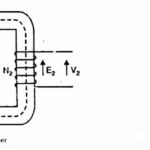
- Primary Winding (N1): Receives the input voltage V1.
- Secondary Winding (N2): Delivers the output voltage V2 to the load.
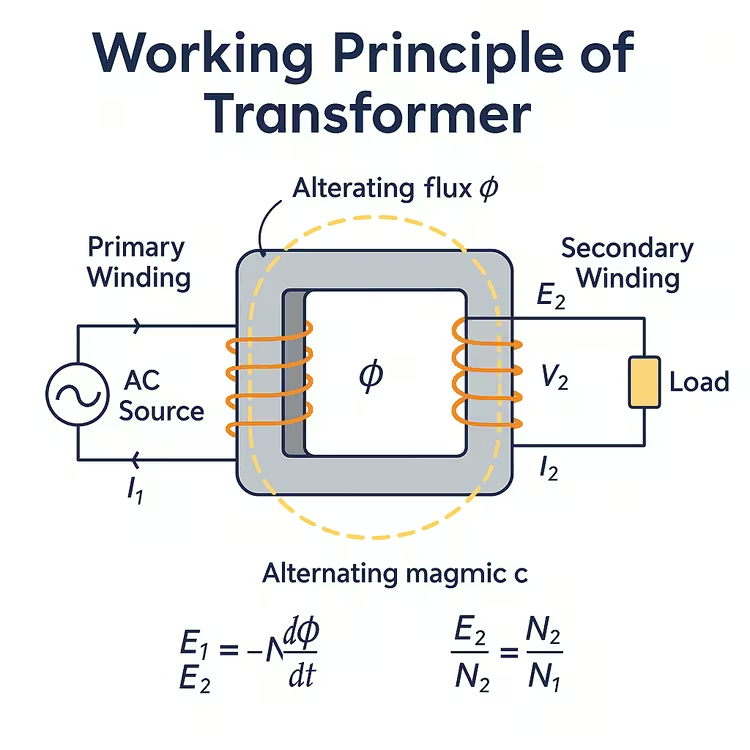
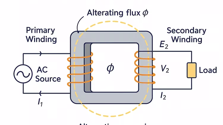
Working Principle: Faraday’s Law of Electromagnetic Induction
Transformers work based on Faraday’s Laws of Electromagnetic Induction. When an AC voltage is applied to the primary winding, it sets up an alternating magnetic flux (φ) in the core. This flux links the primary and secondary windings and induces EMF in both.
The EMF equations are:
E1 = -N1 (dφ/dt)
E2 = -N2 (dφ/dt)
Assuming sinusoidal flux, the RMS value of induced EMF is:
E = 4.44 f N φmax
Voltage Transformation Ratio
The voltage ratio between the windings is directly proportional to the turns ratio:
V2/V1 = N2/N1
- Step-Up Transformer: N2 > N1 ⇒ V2 > V1
- Step-Down Transformer: N2 < N1 ⇒ V2 < V1
Power Transfer and Efficiency
Ideally, the power input equals the power output (excluding losses):
P1 = P2 ⇒ V1 I1 = V2 I2
So, if voltage increases, current must decrease proportionally, and vice versa.
Transformer Losses
Although transformers are highly efficient (95–99%), they experience some losses:
- Core (Iron) Losses: Hysteresis and eddy current losses.
- Copper Losses: Due to resistance in windings: P = I²R
Key Characteristics of Transformers
- Operate only on AC supply.
- No electrical connection between primary and secondary windings — only magnetic coupling.
- No change in frequency between input and output.
- Efficient transfer of energy with negligible mechanical wear.
Applications
- Power transmission and distribution
- Voltage regulation in electronics
- Impedance matching in communication systems
- Isolation between control circuits and power circuits
Frequently Asked Questions (FAQs)
Q1. Why don’t transformers work on DC?
DC provides constant flux, which does not induce EMF in the secondary. Transformers require a changing magnetic field (AC) to operate.
Q2. What reduces eddy current losses in a transformer?
Laminating the core increases resistance to circulating currents, thereby reducing eddy current losses.
Q3. How do you improve transformer efficiency?
Use low-loss core materials, high-quality windings, and proper insulation to reduce iron and copper losses.
Recommended Textbooks
- Electrical Machinery by P.S. Bimbhra
- Principles of Electric Machines and Power Electronics by P.C. Sen
- Electric Machines by I.J. Nagrath and D.P. Kothari
- The Performance and Design of AC Machines by M.G. Say
- Transformers and Inductors for Power Electronics by W.G. Hurley and W.H. Wölfle


Comments are closed.