Electric power control or conditioning requires converting power from one form to another. Power electronic converters perform these power conversion tasks.
A power electronic system consists of one or more power electronic converters. A power electronic converter is made up of power semiconductor devices controlled by integrated circuits.
The switching characteristics of power semiconductor devices permit a power electronic converter to shape the input power of one form to output power of some other form. Static power converters perform these functions of power conversion very efficiently.
Static power converters are electrical networks made of semiconductor devices called switches (SCR, MOSFET, IGBT). They operate by switching these components in a specific sequence to transfer energy between two sources with different electrical properties.
A converter can be seen as a switching matrix. One or more switches are turned on and connected to the supply source to obtain the desired output voltage or current.
Classification of Power Electronic Converters
Power electronics converters (or circuits) can be classified into six types:
- Diode rectifiers
- DC-DC converters (DC choppers)
- DC-AC converters (inverters)
- AC-DC converters (controlled rectifiers)
- AC-AC converters (AC voltage controllers)
- Static switches
The switching devices in the following converters are used to illustrate the basic principles only. The switching action of a converter can be performed by more than one device. The choice of a particular device depends on the voltage, current, and speed requirements of the converter.
1. Diode Rectifiers
A diode rectifier circuit converts AC input voltage into a fixed DC voltage. The input voltage may be single-phase or three-phase.
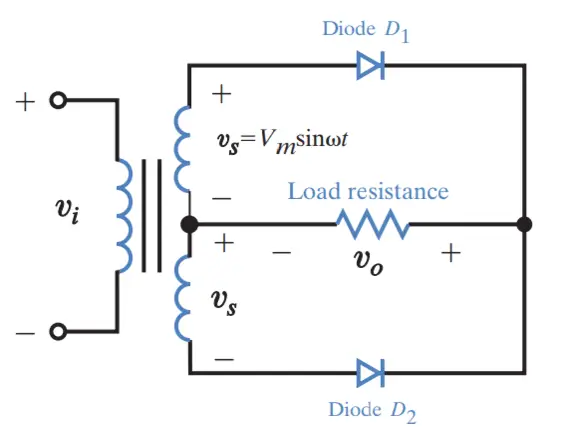
- A diode conducts when its anode voltage is higher than the cathode voltage, typically with a voltage drop around 0.7 V.
- A diode acts as an open circuit when its cathode voltage is higher than the anode voltage, offering high resistance, ideally infinite.
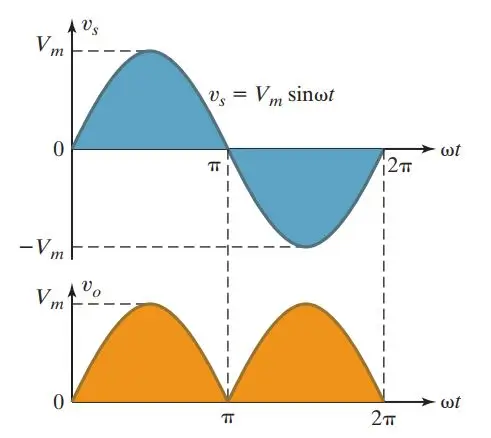
- The output voltage of the rectifier is pulsating DC, containing harmonics and distortion.
- The average output voltage can be calculated using the formula Vo(AVG) = 2Vm/π.
- The input voltage to the rectifier can be either single-phase or three-phase.
Application: Diode rectifiers find wide use in electric traction, battery charging, electroplating, electrochemical processing, power supplies, welding, and uninterruptible power supply (UPS) systems.
2. DC-DC Converters (DC Chopper)
A DC chopper converts fixed DC input voltage to a controllable DC output voltage. Chopper circuits require forced or load commutation to turn off the thyristors. For lower power circuits, thyristors are replaced by power transistors.
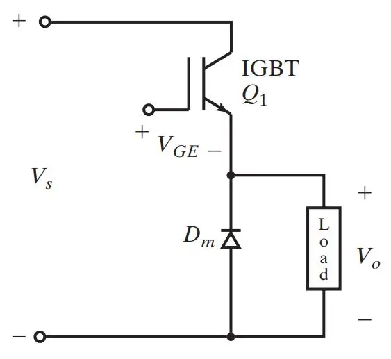
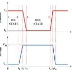
- A DC-DC converter are also known as a chopper or switching regulator is shown in the figure.
- When transistor Q1 is turned on by applying a gate voltage VGE, the DC supply connects to the load, resulting in an instantaneous output voltage of Vo = +Vs.
- When transistor Q1 is turned off by removing the gate voltage VGE, the DC supply disconnects from the load, causing the instantaneous output voltage to be Vo = 0.
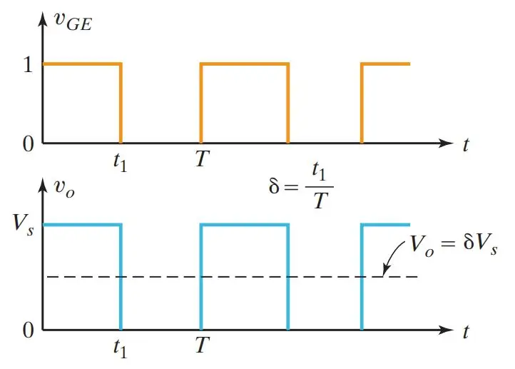
- The average output voltage becomes Vo(AVG) = t1Vs/T = δ Vs, where δ is the duty cycle.
- Therefore, the average output voltage can be varied by controlling the duty cycle.
- The average output voltage Vo is controlled by varying the conduction time t of transistor Q1.
- If T is the chopping period, then t1 = δT, where δ is the duty cycle of the chopper.
Application: Choppers find wide applications in DC drives, subway cars, trolley trucks, battery-driven vehicles, etc.
3. DC to AC Converters (Inverters)
An inverter converts fixed DC voltage to a variable AC voltage. The output may be a variable voltage and variable frequency. These converters use line, load, or forced commutation for turning off the thyristors.
Conventional thyristors are being replaced by GTOs in high-power applications and by power transistors in low-power applications.
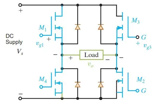
- A single-phase transistor inverter is depicted in the figure above.
- When MOSFETs M1 and M2 are turned on by applying gate voltages, the DC supply voltage Vs appears across the load, resulting in an instantaneous output voltage of Vo = +Vs.
- Similarly, when MOSFETs M3 and M4 are turned on by applying gate voltages, the DC supply voltage Vs appears across the load in the opposite direction, yielding an instantaneous output voltage of Vo = −Vs.
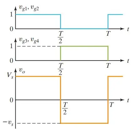
- If transistors M1 and M2 conduct for one half of a period and M3 and M4 conduct for the other half, the output voltage takes on an alternating form.
- The root mean square (rms) value of the output voltage becomes Vo(rms) = VS.
- However, the output voltage contains harmonics which could be filtered out before supplying to the load.
Application: Inverters find wide use in induction-motor and synchronous-motor drives, induction heating, UPS, HVDC transmission, etc.
4. AC to DC Converters (Phase-controlled rectifiers)
These power electronic converter convert constant AC voltage to variable DC output voltage. These rectifiers use line voltage for their commutation, hence also called line-commutated or naturally-commutated AC to DC converters. Phase-controlled converters may be fed from 1-phase or 3-phase sources.
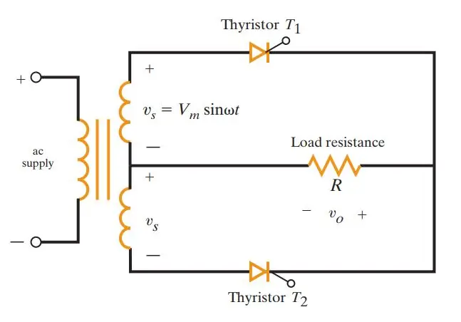
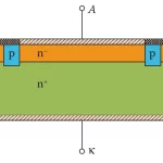
- A single-phase converter with two naturally commutated thyristors is depicted in the figure.
- Thyristors normally remain in an off-state and can be turned on by applying a gate pulse of approximately 10 V with a duration of 100 μs.
- When thyristor T1 is turned on at a delay angle of ωt = α, the supply voltage appears across the load, and thyristor T1 is turned off automatically when its current falls to zero at ωt = π.
- When thyristor T2 is turned on at a delay angle of ωt = π + α, the negative part of the supply voltage appears across the load in the positive direction, and thyristor T2 is turned off automatically when its current falls to zero at ωt = 2π.
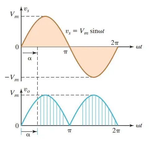
- The average output voltage can be found from Vo(AVG) = (1 + cos α)Vm/π.
- At a delay angle of α = 0, this converter operates as a diode rectifier, as shown above.
- The average value of the output voltage v0 can be controlled by varying the conduction time of thyristors or firing delay angle, α.
- The input could be a single- or three-phase source.
- These converters are also known as controlled rectifiers.
These are used in DC drives, metallurgical and chemical industries, excitation systems for synchronous machines, etc.
5. AC to AC Converters
These type of power electronic converter convert fixed AC input voltage into variable AC output voltage. Two types include:
- AC Voltage Controllers (AC Voltage Regulators): Convert fixed AC voltage directly to variable AC voltage at the same frequency. Widely used for lighting control, speed control of fans, pumps, etc.
- Cycloconverters: Convert input power at one frequency to output power at a different frequency through one-stage conversion. Primarily used for slow-speed large AC drives like rotary kiln, etc.
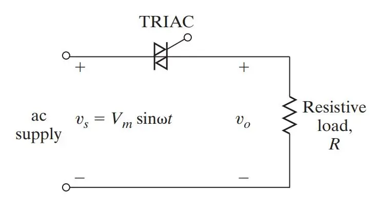
- A single-phase converter with a TRIAC is illustrated in the figure above. This types of converters are also known as AC voltage controllers.
- These converters are utilized to obtain a variable AC output voltage (vo) from a fixed AC source.
- A TRIAC permits current flow in both directions.
- It can be turned on by applying gate voltages at ωt = α for a current flow in the positive direction and also at ωt = π + α for a current flow in the negative direction.
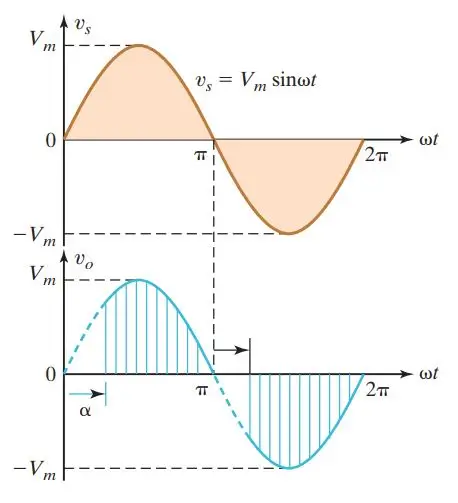
- The output voltage is controlled by varying the conduction time of a TRIAC or firing delay angle, α.
6. Static Switches
Power semiconductor devices can operate as static switches or contactors, offering advantages over mechanical and electromechanical circuit breakers. Depending on the input supply, static switches are called AC static switches or DC static switches.
Static Transfer Switches (STS) are specifically designed to transfer power supply between independent one-phase or three-phase AC power sources. Unlike traditional automatic transfer switches (ATS), STS offers significantly faster load transfer, typically completing the transfer in just 1/4 of a cycle, ensuring uninterrupted operation of sensitive electronic equipment. Additionally, load retransfer to a preferred input source is nearly instantaneous, typically taking only 100 microseconds.
Multiple Conversion
Below is the block diagram of an uninterrupted power supply (UPS). It has multiple power electronic converter circuits such as rectifier, inverter and static switch.
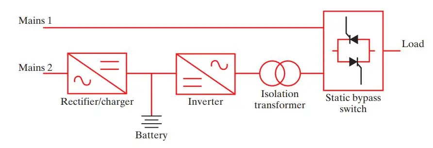
- Multiple conversion stages are often cascaded to produce the desired output, as depicted in the block diagram of UPS.
- Mains 1 supplies the normal AC supply to the load through the static bypass.
- The AC-DC converter charges the standby battery from mains 2.
- The DC-AC converter supplies emergency power to the load through an isolating transformer.
- Mains 1 and mains 2 are normally connected to the same AC supply.
- The input voltage to a rectifier circuit could be either single-phase or three-phase.
- Similarly, an inverter can produce either single-phase or three-phase AC output voltage.
- Consequently, a converter could be either single-phase or three-phase type.
Summary
Table below summarizes different types of power electronic converters, their functions, and their symbols.
| Conversion From/To | Converter Name | Converter Function | Converter Symbol |
|---|---|---|---|
| AC to DC | Rectifier | Converts AC to unipolar (DC) current | 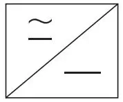 |
| DC to DC | Chopper | Converts constant DC to a variable DC or vice versa | 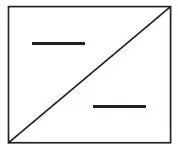 |
| DC to AC | Inverter | Converts DC to AC of desired output voltage and frequency | 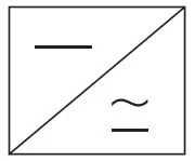 |
| AC to AC | AC Voltage Controller, Cycloconverter, Matrix Converter | Converts AC of desired frequency and/or magnitude from generally line supply AC | 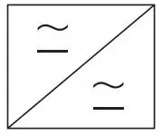 |

Comments are closed.