An automatic transfer switch (ATS) is a crucial component in standby electric systems. They are designed to seamlessly transfer electrical loads from a primary power source (usually the utility or normal power source) to an emergency or standby power source when the normal power supply fails or experiences a significant reduction. The transfer process is automatic and occurs when the emergency power source reaches an acceptable level of voltage and frequency.
What is a Transfer Switch?
A transfer switch is an essential electrical component designed to redirect the power source from its primary origin to a standby source. These switches can be operated either manually or automatically, providing a crucial link between the main power supply and a backup source, often a generator.
The Automatic Transfer Switch (ATS) is a specialized type that is commonly installed in proximity to backup generators, ensuring the seamless transition to temporary electrical power in the event of a utility source failure.
Key features and functions of a transfer switch include:
Operation Modes:
Transfer switches can be manually operated or have automatic functionality. An ATS, in particular, not only switches to the backup generator as a temporary power source but also initiates the generator start-up based on continuous monitoring of specific conditions in the primary feed.
Isolation and Safety:
The transfer switch serves to isolate the backup generator from the electric utility when it is in operation, providing temporary power. This isolation is essential to protect the generator from overload and prevent accidental energization of the service wiring.
Control Capability:
Transfer switches can have manual control only, automatic control, or a combination of both. The switch transition mode can be Open Transition (OT) or Closed Transition (CT).
Functionality in a Home Setup:
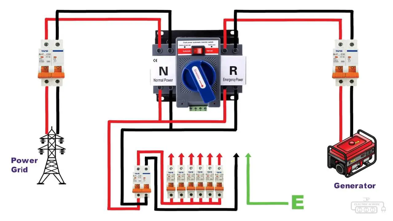
In a home equipped with a backup generator and an ATS, during a utility outage, the ATS initiates the backup generator start-up, breaks the connection to the electric utility, and connects the generator to the home’s main electrical panel. Once the generator is supplying power to the home, it remains disconnected from the electric utility.
Return to Utility Power:
When utility power is restored for a set duration, the transfer switch transfers back to the utility power and commands the generator to turn off after a specified “cool down” period with no load.
Customization and Load Management:
Transfer switches can be configured to provide power to specific critical circuits or entire electrical panels. Some models allow for load shedding or prioritization of optional circuits, offering flexibility in managing power distribution during emergencies.
Advanced Emergency Switchgear:
In large backup generator installations, sophisticated emergency switchgear permits soft loading, facilitating smooth transfer of load between the utility and synchronized generators. This capability is valuable for reducing peak load demand from a utility.
Typical Applications of (ATS)
Automatic transfer switches are engineered to operate seamlessly in a diverse range of applications requiring backup power. These versatile devices find common use in scenarios where a reliable and continuous power supply is essential. Two typical applications are outlined below:
1. Utility–Generator Application:
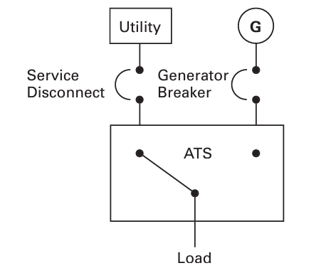
- In this standard configuration, the ATS facilitates the automatic transfer of electrical loads between a utility main source and a generator backup source. This setup is particularly common in emergency and standby power systems.
- During a power outage or reduction in utility power, the transfer switch swiftly and automatically shifts the load circuit to the generator, ensuring uninterrupted power supply to critical loads.
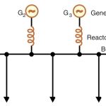
2. Generator–Generator Application:
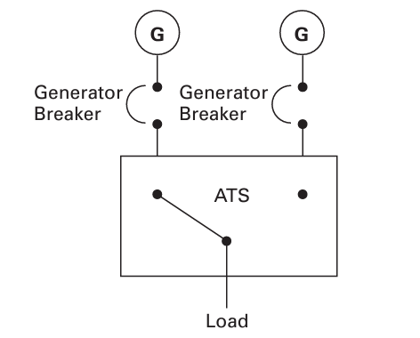
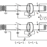
- Figure depicts an alternative application where the ATS is employed between two generator sets. This configuration is often utilized in prime power scenarios, especially in remote installations.
- In generator–generator applications, the transfer switch is used to alternate source power periodically between two generators. This practice ensures an equal sharing of run time between the generator sets.
- Such applications are beneficial in remote locations where a consistent and reliable power source is crucial, and the periodic alternation between generators helps optimize their usage.
Selection of the Size of Automatic Transfer Switch
When determining the size of an automatic transfer switch (ATS), it is crucial to match its rating with the specifications of your main breaker panel. The selection process depends on the desired power coverage during a blackout and the capacity of your generator. Here’s a guideline for choosing the right size:
- Entire Load Coverage:
- If the goal is to power the entire load in the event of a power outage, and your generator is sufficiently large, opt for a transfer switch with a rating identical to your main breaker panel. Typical residential main breaker panels are either 60 amps or, more commonly, 200 amps.
- Install the transfer switch between the main breaker (usually located at the meter) and the main electrical panel to ensure seamless transition and full load coverage.
- Selective Load Coverage:
- If you prefer to run only specific loads during a power outage, consider installing a sub-panel (Emergency Load Management Distribution Board – EMDB) connected to your main panel.
- Choose a transfer switch with an amperage rating based on the specific load requirements rather than the entire panel capacity. This approach is practical when your generator’s capacity is insufficient to power everything simultaneously.
Example Scenario:
- In a home with a 100-amp main feed and a robust 60 kW diesel generator, the generator is capable of powering the entire house. In this case, a transfer switch matching the main breaker panel’s capacity ensures that all household appliances function normally during a power outage.
- Calculations using the formula PGEN=1.73VI*COS∂ (where I = PGEN / 1.73 * V * COS∂) can be employed to determine the amperage requirement. For instance, with a 60,000-watt generator operating at 400 volts and a power factor of 0.8, the calculated amperage (I) is 108A.
Careful consideration of your generator’s capacity and the specific loads you want to power during an outage will guide the selection of the appropriate automatic transfer switch size, ensuring optimal functionality and efficiency in emergency situations.
Related posts:
 Load Break Switches in Electrical Substations
 Low Voltage Fuses: Types and Examples
 High Voltage Fuses: Types and Working
 Current Limiting Reactor or Series Reactor
 Hydraulic Magnetic Circuit Breaker – Construction, Working and Application
 Shunt Reactors: Types, Working and Design
 Substation Bus Configuration / Scheme: The Definitive Guide
 How RCCB/ELCB Protects You from Death?
 How Does Lightning Rods Work?
 Guide To Becoming An Expert In Partial Discharge Testing
Comments are closed.