• Home
  • Courses
  • Machines
    • Transformer
    • AC Motors
      • Induction Motor
      • Synchronous Motor
    • DC Motor
    • DC Generator
  • Power System
    • Circuit Breaker
    • Switchgear
    • Substation
    • Control System
    • Measurement
  • Electronics
  • Blog
  • Contact
    • Contact Us
    • Privacy Policy
Have any question?
[email protected]
RegisterLogin
StudyElectrical.Com
  • Home
  • Courses
  • Machines
    • Transformer
    • AC Motors
      • Induction Motor
      • Synchronous Motor
    • DC Motor
    • DC Generator
  • Power System
    • Circuit Breaker
    • Switchgear
    • Substation
    • Control System
    • Measurement
  • Electronics
  • Blog
  • Contact
    • Contact Us
    • Privacy Policy

Circuit Breaker

Breaker Failure Relay (Back-up Protection Relay)

  • Categories Circuit Breaker, Electrical Relays, Power System, Substation, Switchgear
Breaker failure relay
Each year as line and system loading increase and more operating companies superimpose higher voltage transmission systems on existing facilities, the need for high-speed fault clearing, particularly in the face of a relay or circuit breaker failure, is accentuated.
Breaker failure relay

In such instances, the answer is invariable local back-up protection for circuit breaker failure and, in many cases, local back-up protection for relay failure. In some instances, the need for positive, high-speed clearing of all faults is so acute that two separate sets of primary relaying have been employed, with one set arbitrarily designated as a back-up.

The primary objective of back-up protection is to open all sources of generation to an uncleared fault on the system. To accomplish this objective, an adequate back-up protective system must meet the following functional requirements:

  1. It must recognize the existence of all faults which occur within its prescribed zone of protection.
  2. It must detect the failure of the primary protection to clear any fault as planned
  3. In clearing the fault from the system, it must
    • Initiate the tripping of the minimum number of circuit breakers.
    • Operate fast enough (consistent with coordination requirements) to maintain system stability, prevent excessive equipment damage, and maintain a prescribed degree of service continuity.

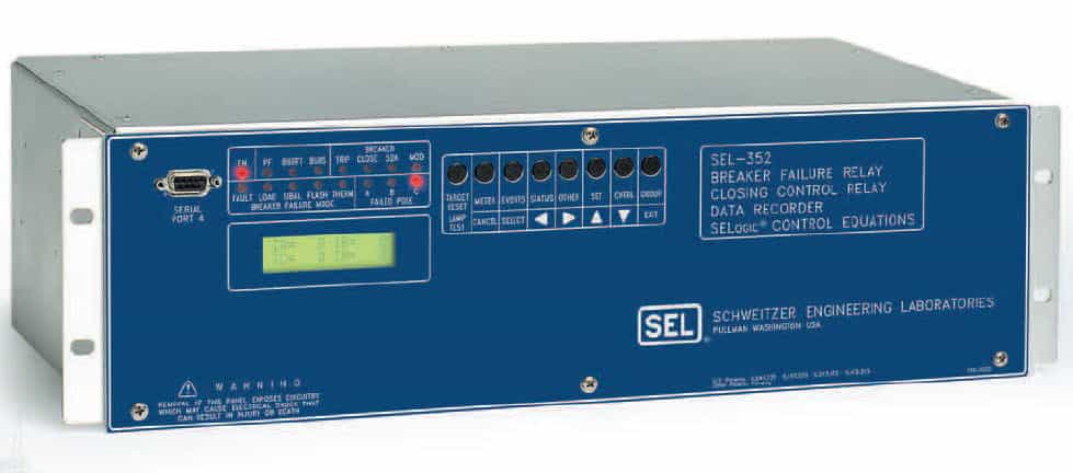
Breaker failure relays are required to give a rapid trip when the primary circuit breaker does not break properly at e.g. a short circuit in the network. The faulty section of the network could in this way be tripped separately.

Breaker failure relays are referred to as back-up protection devices which are applied as stoppage protection relays for the most relays. As a case in point breaker failure relay is employed as a backup device for the differential relay of an influence power transformer and additionally for distance relay of a conductor.

Why Breaker Failure?

In the fault condition of any equipment, it is expected that the circuit breaker of this equipment will be tripped by the main protection relays of such equipment if there is a failure in the tripping circuit of the circuit breaker or in the circuit breaker itself.

In this case, the circuit breaker will not be tripped and so, to isolate this fault, the bus bar at which this equipment is connected must be completely isolated by tripping all the equipment connected to it by a delayed time.

Then, the only connected equipment to this bus bar is the faulted one. In this case, the faulted equipment has no current passing through it so, it is can be disconnected manly by isolates.

How Breaker Failure Relay Operate?

There are three conditions must be satisfied for the operation of breaker failure relay which are

  • Tripping signals from any main protection relay of the faulted equipment are exist.
  • The circuit breaker of the faulted equipment is still connected (n.o. auxiliary contact from a circuit breaker is used).
  • There is current passing through this equipment even if it is valued is very small.
Although one of the second and third conditions is sufficient for the healthy operation of the breaker failure relay, it is preferable to use both for more security.
Wiring diagram of breaker failure circuit

The figure shows the wiring diagram of the breaker failure circuit. Tripping circuit of breaker failure relay is similar to the tripping circuit of the bus bar protection relay. In general breaker failure relay may use the same tripping circuit of bus bar protection relay.

Related Articles

  • circuit breaker rating
    Circuit Breaker Ratings

    The rating of circuit breaker is given according to the duties that are performed by…

  • interview question circuit breaker
    Circuit Breakers - Interview Questions with Answers

    1. What is a Circuit Breaker? Circuit Breaker is a mechanical device designed to close…

  • overcurrent relay
    Overcurrent Relays for Transmission Line Protection

    The use of overcurrent relays is the simplest and cheapest type of line protection. Three…

  • types of electrical relays
    Types of Electrical Relays

    We have already discussed the working of electrical relays. Now we are going through different…

  • Circuit-Breaker-Working-Principle.gif
    Circuit Breaker Definition, Working Principle and Arcing Phenomenon

    Definition A circuit breaker means the device which breaks (Open) the circuit under the abnormal…

  • ACB Air Circuit Breaker
    Working of Air Circuit Breakers

    What is an ACB? A circuit breaker in which the contacts open and close in…

  • Share:
author avatar
Electrical Engineer

Previous post

Why Birds don't get Electrocuted on Touching Power Lines?
July 16, 2015

Next post

What is Switchgear? | Features, Components and Classification
July 19, 2015

You may also like

percentage_reactance transformer
Percentage Reactance in Power System (Transformer, Generator or Reactor)
16 January, 2023
Load Curve and Load Duration Curve
Load Duration Curve in Power Station
29 September, 2022
Double end break disconnect switch
Disconnect Switches (Isolator) in Substation: Types, Design and Working
1 September, 2022

Leave A Reply Cancel reply

Your email address will not be published. Required fields are marked *

Search Here

From Blog

Automatic Irrigation System Using Arduino
20Dec2017
Induction Motor and Transformer
Comparison between Induction Motor and Transformer
01Mar2018
Circuit-Breaker-Working-Principle.gif
Circuit Breaker Definition, Working Principle and Arcing Phenomenon
08Dec2018
Arduino Digital Voltmeter
Arduino DC Digital Voltmeter
18Oct2017

Categories

  • Alternator
  • Arduino
  • Basic Electrical
  • Battery
  • Books
  • Cables
  • Capacitor
  • Career
  • Circuit Breaker
  • Control System
  • DC Generator
  • DC Motor
  • Drives
  • Electric Vehicles
  • Electrical Circuits
  • Electrical Machines
  • Electrical Relays
  • Electrical Safety
  • Electronics
  • Embedded System
  • Exams
  • Generation
  • Guest Post
  • HVDC
  • Instrumentation
  • Interview Questions
  • Locomotives
  • Measurement
  • Microcontroller
  • Objective Questions
  • PCB
  • PLC
  • Power System
  • Problems and Solution
  • Projects
  • Resistor
  • Signals and Systems
  • Single Phase Motors
  • Substation
  • Switchgear
  • Synchronous Motor
  • Three Phase Induction Motor
  • Transformer
  • Transmission Line
  • Uncategorized

Copyright © 2021 Study Electrical, Inc.

© StudyElectrical.Com 2021

Login with your site account

Lost your password?

Not a member yet? Register now

Register a new account

Are you a member? Login now