• Home
  • Courses
  • Machines
    • Transformer
    • AC Motors
      • Induction Motor
      • Synchronous Motor
    • DC Motor
    • DC Generator
  • Power System
    • Circuit Breaker
    • Switchgear
    • Substation
    • Control System
    • Measurement
  • Electronics
  • Blog
  • Contact
    • Contact Us
    • Privacy Policy
Have any question?
[email protected]
RegisterLogin
StudyElectrical.Com
  • Home
  • Courses
  • Machines
    • Transformer
    • AC Motors
      • Induction Motor
      • Synchronous Motor
    • DC Motor
    • DC Generator
  • Power System
    • Circuit Breaker
    • Switchgear
    • Substation
    • Control System
    • Measurement
  • Electronics
  • Blog
  • Contact
    • Contact Us
    • Privacy Policy

Basic Electrical

Insulators, Conductors and Semiconductors (with Band Diagram)

  • Categories Basic Electrical, Electronics
Energy band diagram of conductor semiconductor insulator

Solid state materials can be classified into three groups:

  1. insulators,
  2. semiconductors
  3. conductors. 

Insulators have no free charge carriers available with them under normal conditions.

Conducting materials have plenty of free electrons available for electric conduction.

A semiconductor material is one whose electrical properties lie in between those of insulators and good conductors.

  • Insulators are materials having an electrical conductivity less than 10-8 S/cm (like diamond: 10-16 S/cm);
  • semiconductors have a conductivity between 10-8 S/cm and 103 S/cm (for silicon it can range from 10-5 S/cm  to 103 S/cm );
  • at last conductors are materials with high conductivities, greater than 103 S/cm :(like silver: 106 S/cm.)

The electrical conduction properties of different elements and compounds can be explained in terms of the electrons having energies in the valence and conduction bands. The electrons lying in the lower energy bands. which are normally filled. play no part in the conduction process. 

Table of Contents

  • Insulators
  • Conductors
  • Semiconductors
  • Comparison between Conductor, Semiconductor and Insulator
    • Related Articles

Insulators

Stated simply, insulators are those materials in which valence electrons are bound very tightly to their parent atoms, thus requiring a very large electric field to remove them from the attraction of their nuclei.

energy-band-level-diagram-of-insulator
Energy band level diagram of insulator

In other words, insulators have no free charge carriers available with them under normal conditions. 

In terms of energy bands, it means that insulators [Fig(a)] have a full valence band, 

  1. have an empty conduction band, 
  2. have a large energy gap (of several eV) between them and 
  3. at ordinary temperatures, the probability of electrons from full valence band gaining sufficient energy so as to surmount energy gap and thus become available for conduction in the conduction band, is slight. 
Energy Band diagram of Conductors, Semiconductors and Insulators

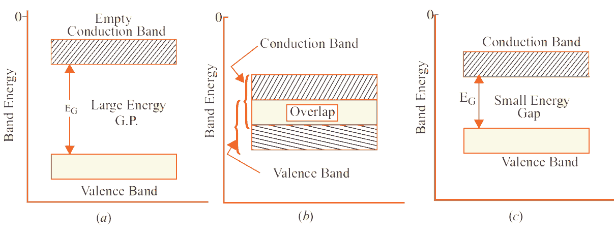
This is shown in Fig(a). For conduction to take place, electrons must be given sufficient energy to jump from the valence band to the conduction band.

Increase in temperature enables some electrons to go to the conduction band which fact accounts for the negative resistance temperature coefficient of insulators. 

Conductors

Put in a simple way, conducting materials are those in which plenty of free electrons are available for electric conduction. 

In terms of energy bands, it means that electrical conductors are those which have overlapping valence and conduction bands as shown in Fig (b). 

energy-band-level-diagram-of-conductor
Energy band level diagram of conductor

In fact, there is no physical distinction between the two bands. Hence, the availability of a large number of conduction electrons. 

Another point worth noting is that in the absence of forbidden energy gap in good conductors, there is no structure to establish holes.

The total current in such conductors is simply allowed of electrons. It is exactly for this reason that the existence of holes was not discovered until semiconductors were studied thoroughly. 

Semiconductors

A semiconductor material is one whose electrical properties lie in between those of insulators and good conductors. Examples are germanium and silicon. 

In terms of energy bands, semiconductors can be defined as those materials which have almost an empty conduction band and almost filled valence band with a very narrow energy gap (of the order of 1 eV) separating the two. 

energy-band-level-diagram-of-semiconductor
Energy-band-level-diagram-of-semiconductor

At 0°K, there are no electrons in the conduction band and the valence band is completely filled.

However, with an increase in temperature, the width of the forbidden energy bands is decreased so that some of the electrons are liberated into the conduction band.

In other words, the conductivity of semiconductors increases with temperature. 

Moreover, such departing electrons leave behind positive holes in the valence band. Hence, the semiconductor current is the sum of electron and hole currents flowing in opposite directions. 

Comparison between Conductor, Semiconductor and Insulator

ParameterConductorSemiconductorInsulator
Forbidden energy gapNot existSmall (1 eV)Large (>5 eV)
ConductivityHigh (10-7 mho/m)Medium (10-7 to 10-13 mho/m)Very Low (10-3 mho/m)
Almost negligible.
ResistivityLowModerateHigh
Flow of currentDue to movement of free electrons.Due to movement of electrons and holes.Almost negligible but only due to free electrons.
Temperature coefficient of resistancePositiveNegativeNegative
Charge carriers in conduction bandCompletely filledPartially filledCompletely vacant
Charge carriers in valence bandAlmost vacantPartially filledCompletely filled
ExampleCopper, Aluminium, graphite etc.Silicon, Germanium, arsenic etc.Paper, rubber, glass, plastic etc.
ApplicationsConducting wires, Transformers, in electrical cords etc.Diodes, transistors, optocouplers etc.Sports equipment, home appliances etc.

Related Articles

  • Bundled-conductor
    Bundled Conductors in Transmission Lines

    The combination of more than one conductor per phase in parallel suitably spaced from each…

  • ladder diagram
    What is Ladder Diagram and How to Draw a Ladder Diagram?

    This is a continuation of the previous article (Introduction to PLC Ladder Programming) in PLC…

  • aeolian vibration
    Aeolian Vibration of Transmission Conductors

    What is Aeolian Vibration? Aeolian vibration is a type of motion caused by wind on…

  • 4 2Bmajor 2Btypes 2Bof 2Bsubstations
    4 Major Types of Electrical Substations

      The assembly of the apparatus used to change some characteristic (e.g. voltage, a.c. to…

  • ELECTRICAL IMPEDANCE MADE EASY
    Video Tutorial: Electrical Impedance - A Practical View

    In this two part video series we discuss the basics of electrical impedance from a…

  • engineering students working in the lab PESV4KM
    What do Electrical Engineers Do?

    An electrical engineer is someone who designs and develops new electrical equipment, solves problems and…

  • Share:
author avatar
Electrical Engineer

Previous post

Swinburne’s Test of DC Machine (Generator and Motor)
May 23, 2015

Next post

Residual Current Protective Devices (RCCB, ELCB & RCBO)
May 30, 2015

You may also like

Thin film application iin electronics
The Various Applications Of Thin Films In Electronics And Other Equipment
16 January, 2023
Thin film resistors
Applications & Functions of Thin Film Resistors
12 January, 2023
multimeter
Digital Multimeter: Working and Application
8 July, 2022

    6 Comments

  1. clad
    May 25, 2019
    Reply

    This is perfectly written and I completely agree!

  2. Paaff
    May 28, 2019
    Reply

    this was great info!

  3. Cherdic
    May 28, 2019
    Reply

    good post

  4. buffic
    May 28, 2019
    Reply

    I don’t get it

  5. best classified ad sites
    June 2, 2019
    Reply

    loved it

Leave A Reply Cancel reply

Your email address will not be published. Required fields are marked *

Search Here

From Blog

Arduino Digital Voltmeter
Arduino DC Digital Voltmeter
18Oct2017
Construction of High Voltage Current Transformer
Basic Types of Current Transformers
26Oct2015
Effects of Voltage and Frequency Variation on Transformers
12Aug2014
Types of analog instruments
Three Types of Analog Instruments
28Aug2017

Categories

  • Alternator
  • Arduino
  • Basic Electrical
  • Battery
  • Books
  • Cables
  • Capacitor
  • Career
  • Circuit Breaker
  • Control System
  • DC Generator
  • DC Motor
  • Drives
  • Electric Vehicles
  • Electrical Circuits
  • Electrical Machines
  • Electrical Relays
  • Electrical Safety
  • Electronics
  • Embedded System
  • Exams
  • Generation
  • Guest Post
  • HVDC
  • Instrumentation
  • Interview Questions
  • Locomotives
  • Measurement
  • Microcontroller
  • Objective Questions
  • PCB
  • PLC
  • Power System
  • Problems and Solution
  • Projects
  • Resistor
  • Signals and Systems
  • Single Phase Motors
  • Substation
  • Switchgear
  • Synchronous Motor
  • Three Phase Induction Motor
  • Transformer
  • Transmission Line
  • Uncategorized

Copyright © 2021 Study Electrical, Inc.

© StudyElectrical.Com 2021

Login with your site account

Lost your password?

Not a member yet? Register now

Register a new account

Are you a member? Login now