• Home
  • Courses
  • Machines
    • Transformer
    • AC Motors
      • Induction Motor
      • Synchronous Motor
    • DC Motor
    • DC Generator
  • Power System
    • Circuit Breaker
    • Switchgear
    • Substation
    • Control System
    • Measurement
  • Electronics
  • Blog
  • Contact
    • Contact Us
    • Privacy Policy
Have any question?
[email protected]
RegisterLogin
StudyElectrical.Com
  • Home
  • Courses
  • Machines
    • Transformer
    • AC Motors
      • Induction Motor
      • Synchronous Motor
    • DC Motor
    • DC Generator
  • Power System
    • Circuit Breaker
    • Switchgear
    • Substation
    • Control System
    • Measurement
  • Electronics
  • Blog
  • Contact
    • Contact Us
    • Privacy Policy

    PLC

    What is Ladder Diagram and How to Draw a Ladder Diagram?

    • Categories PLC
    ladder diagram

    This is a continuation of the previous article (Introduction to PLC Ladder Programming) in PLC Programming series. Please go through an introduction to Ladder Programming before reading this post.

    In this post, we will discuss about what is a ladder diagram and how to draw a ladder diagram.

    Ladder Diagram

    A very commonly used method of programming PLCs is based on the use of ladder diagrams. 
     
    Writing a program is then equivalent to drawing a switching circuit. The ladder diagram consists of two vertical lines representing the power rails. Circuits are connected as horizontal lines, i.e. the rungs of the ladder, between these two verticals.

    How to Draw a Ladder Diagram?

    In drawing a ladder diagram, certain conventions are adopted:

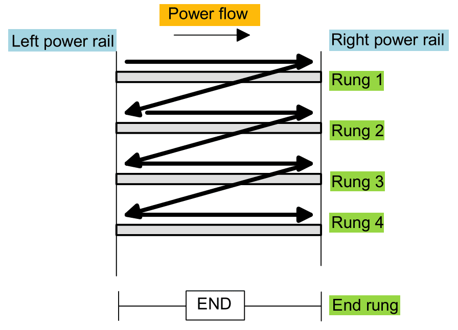
    The vertical lines of the diagram represent the power rails between which circuits are connected. The power flow is taken to be from the left-hand vertical across a rung.

    Each rung on the ladder defines one operation in the control process.

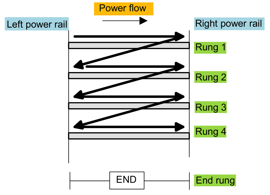
    A ladder diagram is read from left to right and from top to bottom. The figure shows the scanning motion employed by the PLC. The top rung is read from left to right.

    Then the second rung down is read from left to right and so on. When the PLC is in its run mode, it goes through the entire ladder program to the end, the end rung of the program is clearly denoted, and then promptly resumes at the start. This procedure of going through all the rungs of the program is termed a cycle. The end rung might be indicated by a block with the word END or RET for return since the program promptly returns to its beginning.

    2017 08 21 11h33 11

    Each rung must start with an input or inputs and must end with at least one output. The term input is used for control action, such as closing the contacts of a switch, used as an input to the PLC. The term output is used for a device connected to the output of a PLC, e.g. a motor.

    Electrical devices are shown in their normal condition. Thus a switch which is normally open until some object closes it is shown as open on the ladder diagram. A switch that is normally closed is shown closed.

    A particular device can appear in more than one rung of a ladder. For example, we might have a relay which switches on one or more devices. The same letters and/or numbers are used to label the device in each situation.

    The inputs and outputs are all identified by their addresses, the notation used depending on the PLC manufacturer. This is the address of the input or output in the memory of the PL.
    Related Articles

    • plc 2
      Introduction to PLC Ladder Programming

      We have already discussed the introduction to programmable logic controllers. Please go through it before…

    • Energy band diagram of conductor semiconductor insulator
      Insulators, Conductors and Semiconductors (with Band Diagram)

      Solid state materials can be classified into three groups: insulators, semiconductors conductors.  Insulators have no…

    • Programmable%2Blogic%2Bcontroller%2BPLC%2BLectures%2BNotes
      14 Lectures on Programmable Logic Controllers (PLC)

      A PLC is a user-friendly, microprocessor based specialized computer that carries out control functions of…

    • Programmable Logic Controllers
      The Basics of Programmable Logic Controller (PLC) that You Never Learned

      Programmable Logic Controllers (PLCs) are also referred to as programmable controllers in some places. They…

    • introduction to programmable logic controller
      Introduction to Programmable Logic Controllers (PLCs)

      What is a Programmable Logic Controller (PLC)? A programmable logic controller, PLC, or programmable controller is a…

    • arduino program structure
      How to Structure an Arduino Program?

      If you are new to programming and want to understand how Arduino programs work, read…

    • Share:
    author avatar
    Electrical Engineer

    Previous post

    Introduction to PLC Ladder Programming
    August 21, 2017

    Next post

    Three Types of Analog Instruments
    August 28, 2017

    You may also like

    Programmable Logic Controllers
    The Basics of Programmable Logic Controller (PLC) that You Never Learned
    28 March, 2020
    plc_2
    Introduction to PLC Ladder Programming
    2 August, 2017
    introduction to programmable logic controller
    Introduction to Programmable Logic Controllers (PLCs)
    9 October, 2015

      1 Comment

    Leave A Reply Cancel reply

    Your email address will not be published. Required fields are marked *

    Search Here

    From Blog

    What Are Military Materials?
    28Jun2021
    protective zones in power system
    Protective Zones in Power Systems
    21Sep2016
    Air Variable Capacitor
    How Charge is Stored in a Dielectric?
    28Feb2020
    Testing a DC Motor
    Speed Control of DC Motor (Shunt, Series and Compound)
    28Nov2013

    Categories

    • Alternator
    • Arduino
    • Basic Electrical
    • Battery
    • Books
    • Cables
    • Capacitor
    • Career
    • Circuit Breaker
    • Control System
    • DC Generator
    • DC Generator MCQ
    • DC Generator Solved Problems
    • DC Motor
    • DC Motor MCQ
    • Drives
    • Electric Vehicles
    • Electrical Circuits
    • Electrical Machines
    • Electrical Relays
    • Electrical Safety
    • Electronics
    • Embedded System
    • Exams
    • Generation
    • Guest Post
    • HVDC
    • Instrumentation
    • Interview Questions
    • Locomotives
    • MCQ
    • Measurement
    • Microcontroller
    • Objective Questions
    • PCB
    • PLC
    • Power System
    • Problems and Solution
    • Projects
    • Resistor
    • Signals and Systems
    • Single Phase Motors
    • Substation
    • Switchgear
    • Synchronous Motor
    • Three Phase Induction Motor
    • Transformer
    • Transmission Line
    • Uncategorized

    Copyright © 2021 Study Electrical, Inc.

    © StudyElectrical.Com 2021

    Login with your site account

    Lost your password?

    Not a member yet? Register now

    Register a new account

    Are you a member? Login now