An alternator operates on the same fundamental principle of electromagnetic induction as a DC generator i.e., when the flux linking a conductor changes, an e.m.f. is induced in the conductor.
Like a DC generator, an alternator also has an armature winding and a field winding. But there is one important difference between the two.
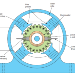
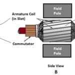
In a DC generator, the armature winding is placed on the rotor in order to provide a way of converting alternating voltage generated in the winding to a direct voltage at the terminals through the use of a rotating commutator.
The field poles are placed on the stationary part of the machine. Since no commutator is required in an alternator, it is usually more convenient and advantageous to place the field winding on the rotating part (i.e., rotor) and armature winding on the stationary part (i.e., stator).
Advantages of Stationary Armature
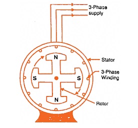
The 3-phase armature winding is placed on the stator. This arrangement has the following advantages:
- It is easier to insulate stationary winding for high voltages for which the alternators are usually designed. It is because they are not subjected to centrifugal forces and also extra space is available due to the stationary arrangement of the armature.
- The stationary 3-phase armature can be directly connected to load without going through large, unreliable slip rings and brushes.
- Only two slip rings are required for d.c. supply to the field winding on the rotor. Since the exciting current is small, the slip rings and brush gear required are of light construction.
- Due to the simple and robust construction of the rotor, the higher speed of rotating DC field is possible. This increases the output obtainable from a machine of given dimensions.
Note: All alternators above 5 kVA employ a stationary armature (or stator) and a revolving d.c. field.



Comments are closed.