
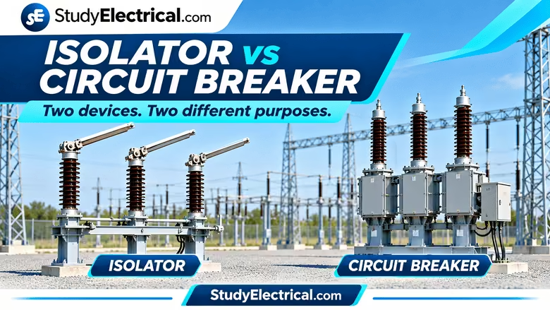
Electrical power systems require switching devices to control the flow of electricity, protect equipment and provide safe conditions for maintenance. Two important devices commonly found in substations and electrical installations are the isolator (disconnect switch) and the circuit breaker.
Although both devices are used to open and close electrical circuits, they perform different functions.
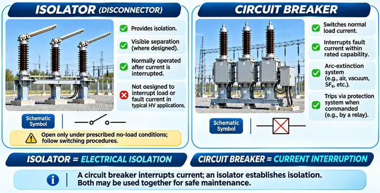
A circuit breaker is designed to switch electrical circuits and interrupt current under specified normal and fault conditions. An isolator, on the other hand, is primarily used to provide electrical isolation so that equipment can be safely inspected or maintained.
Understanding the difference between an isolator and a circuit breaker is fundamental to learning electrical switchgear, power system protection and substation operation.
In this guide, we will explore their functions, working principles, construction, applications, differences and how they work together in a typical substation.
What Is an Isolator?
An isolator, also called a disconnect switch or disconnector, is a mechanical switching device used to isolate a section of an electrical circuit or equipment from the source of power.
Its primary purpose is to provide a visible open gap between the energized system and the isolated equipment, allowing maintenance personnel to establish a safe isolation condition according to the applicable operating procedure.
Isolators are commonly installed in electrical substations to isolate circuit breakers, transformers, transmission lines, busbars and other equipment.
For a more detailed explanation of isolator construction, types and operating mechanisms, read our guide on Disconnect Switches in Substation: Types, Design and Working.
Main Functions of an Isolator
The main functions of an isolator include:
- Providing electrical isolation of equipment for maintenance.
- Establishing a visible break in the electrical circuit where the design permits.
- Isolating equipment from other parts of the electrical system.
- Providing isolation points in busbar arrangements and substation bays.
- Supporting safe maintenance procedures when used with interlocks, earthing switches and other safety measures.
How Does an Isolator Work?
An isolator operates by mechanically separating its contacts. When the isolator is in the open position, an air gap or another designed insulating separation is established between its contacts.
In a typical high-voltage substation, an isolator is not intended to interrupt normal load current or short-circuit current. Therefore, the associated circuit breaker is normally opened before the isolator is operated, following the approved switching procedure.
When the isolator is closed, its contacts connect the two sides of the circuit and allow current to flow through the connected equipment.
When the isolator is opened, the electrical connection is removed, creating an isolation point.
The visible separation provided by an isolator is particularly important during maintenance because it helps personnel verify the physical disconnection of the equipment.
Important note: Some specially designed disconnectors have specific switching capabilities, such as switching certain bus-charging, transformer-magnetizing or other defined currents. They must only be operated within their specified ratings and approved procedures.
What Is a Circuit Breaker?
A circuit breaker is a mechanical switching device capable of making, carrying and breaking current under specified normal circuit conditions. It is also capable of making, carrying for a specified time and breaking current under specified abnormal conditions, such as short circuits.
Circuit breakers are essential components of electrical protection systems. They protect electrical circuits, equipment and power system components against damage caused by faults.
Circuit breakers are installed in residential distribution boards, industrial installations, motor control systems, generating stations, transmission networks and electrical substations.
For a deeper understanding of circuit breaker construction, arc formation, working principles and interruption methods, see our complete guide to Circuit Breakers.
Main Functions of a Circuit Breaker
A circuit breaker performs the following functions:
- Switching electrical circuits during normal operation.
- Carrying normal load current continuously within its rating.
- Interrupting overload or fault current within its rated capabilities.
- Disconnecting faulty sections of an electrical system.
- Operating through manual, electrical, remote-control or protective-trip commands, depending on its design.
How Does a Circuit Breaker Work?
A circuit breaker contains fixed and moving contacts. During normal operation, these contacts remain closed, allowing current to flow through the circuit.
When the circuit breaker receives an opening command, its operating mechanism separates the contacts.
If current is flowing through the circuit at the moment the contacts separate, an electrical arc may form between them. This arc must be extinguished safely to interrupt the current.
Circuit breakers use different arc-extinction techniques depending on their voltage level and construction.
Common circuit breaker types include:
- Air Circuit Breaker (ACB)
- Vacuum Circuit Breaker (VCB)
- SF₆ Circuit Breaker
- Oil Circuit Breaker
- Miniature Circuit Breaker (MCB)
- Moulded Case Circuit Breaker (MCCB)
How Does a Circuit Breaker Interrupt Fault Current Automatically?
In a protected electrical system, the circuit breaker normally works together with a protection system.
The sequence is:
- A fault occurs in the electrical system.
- A current transformer or other sensing device detects the electrical condition.
- The protective relay evaluates the measured quantities and identifies the fault according to its protection settings.
- The protective relay sends a trip command to the circuit breaker.
- The circuit breaker operating mechanism opens its contacts.
- The arc is extinguished and the faulty circuit is interrupted, within the breaker’s capability.
A circuit breaker does not necessarily detect every fault by itself. In high-voltage substations, protective relays are usually responsible for detecting faults and issuing trip commands to the circuit breaker.
Isolator vs Circuit Breaker: Key Differences
The isolator and circuit breaker have different operating principles and purposes.
| Feature | Isolator | Circuit Breaker |
|---|---|---|
| Main purpose | Electrical isolation | Switching and current interruption |
| Primary role | Isolate equipment for maintenance | Control and interrupt electrical circuits |
| Load current interruption | Generally not designed for this duty in typical HV isolator applications | Designed within its rated switching capability |
| Fault current interruption | Not designed to interrupt fault current | Designed to interrupt specified fault current |
| Arc-extinction system | Generally no arc-extinction system for interrupting load/fault current | Arc-extinction mechanism is provided |
| Operating condition | Normally operated after the circuit is interrupted and under prescribed conditions | Can operate under normal load and specified fault conditions |
| Automatic protection operation | Normally not used as the fault-interrupting device | Commonly tripped by protective relays |
| Visible isolation | Often provides a visible isolation gap | Contact separation may not provide a visible external isolation gap |
| Typical application | Maintenance isolation of lines, transformers, busbars and other equipment | Switching, protection and interruption of lines, transformers and other circuits |
Why Do We Need Both an Isolator and a Circuit Breaker?
You may wonder why a substation requires both an isolator and a circuit breaker if both can open an electrical circuit.
The answer is that interrupting current and providing safe isolation are two different requirements.
A circuit breaker is designed to interrupt current. It may open automatically during a fault and can also be operated manually or remotely.
However, a circuit breaker alone may not provide the visible isolation required for maintenance.
An isolator provides a physical separation point that can be used to establish the isolation condition required by the maintenance procedure.
Therefore, both devices are used together in many substation arrangements.
Example: Isolating a Transmission Line for Maintenance
Consider a transmission line connected to a substation busbar through a circuit breaker and isolators.
When the transmission line needs to be taken out of service for maintenance, the switching operation is generally performed in a controlled sequence.
Typical isolation sequence:
- Open the circuit breaker to interrupt the load current.
- Confirm the circuit breaker has opened and the circuit is in the required condition.
- Open the relevant isolators according to the approved switching procedure.
- Verify the isolation and absence of voltage using the prescribed method.
- Close the earthing switch, where provided and permitted by the approved procedure.
- Apply additional safety precautions, permits and worksite protection required for the maintenance.
The exact sequence may vary depending on the substation arrangement, interlocking scheme, equipment design and operating rules.
An isolator should not be treated as a substitute for a circuit breaker when interrupting load or fault current.
Isolator and Circuit Breaker in a Substation
In a typical high-voltage substation bay, the circuit breaker and isolators are arranged to allow switching, protection and maintenance isolation.
A simplified arrangement may include:
Main Bus → Bus Isolator → Circuit Breaker → Line Isolator → Current Transformer → Transmission Line
The actual arrangement may include additional equipment such as:
- Earthing switches
- Current transformers
- Voltage transformers or CVTs
- Wave traps
- Lightning arresters
- Busbar selector isolators
- Additional isolators
- Protective relays and control equipment
To understand how these devices fit into the overall substation, read our guide on Electrical Substation: Equipment, Types, Components & Functions.
Role of the Circuit Breaker in a Substation
The circuit breaker controls the connection of a line or equipment to the electrical system. It can interrupt load current and fault current within its ratings.
When a fault occurs, the associated protection system detects the fault and trips the circuit breaker to disconnect the faulty section.
Role of the Isolator in a Substation
The isolator provides the required isolation point after the circuit has been switched off.
It helps maintenance personnel establish a physically separated section of the circuit, subject to verification and the required safety procedure.
Difference Between Isolator, Circuit Breaker and Earthing Switch
These three devices are often found together in high-voltage substations, but their functions are different.
| Device | Main function |
|---|---|
| Isolator | Separates a circuit or equipment from the source to establish isolation |
| Circuit Breaker | Makes, carries and interrupts current under specified normal and fault conditions |
| Earthing Switch | Connects an isolated section to earth to establish an earthing condition for safety |
An isolator provides isolation, a circuit breaker interrupts current, and an earthing switch establishes an earth connection.
They are often mechanically or electrically interlocked to prevent unsafe operating sequences.
These devices are part of the wider electrical switchgear system, which is responsible for switching, protection and isolation of electrical circuits and equipment.
Isolator vs Circuit Breaker – Simple Example
Think of an electrical circuit as a road carrying vehicles.
- Circuit breaker: A controlled barrier that can stop the flow of traffic even when vehicles are moving.
- Isolator: A physical separation point that is established after traffic has been stopped, allowing a section of the road to be safely separated for maintenance.
This analogy helps understand why both devices are required.
The circuit breaker stops the electrical current. The isolator establishes the isolation point.
Frequently Asked Questions (FAQs)
Can an isolator interrupt load current?
In typical high-voltage substation applications, isolators are not designed to interrupt normal load current. The circuit breaker is normally opened first. Some disconnectors have specific switching capabilities, but they must only be used within their defined ratings.
Can an isolator interrupt short-circuit current?
A conventional isolator is not designed to interrupt short-circuit current. Fault current must be interrupted by a suitable circuit breaker or another rated interrupting device.
Why is the circuit breaker opened before the isolator?
The circuit breaker is used to interrupt the current before operating a conventional isolator. Opening an isolator under load can produce an arc that the device is not designed to extinguish.
Does a circuit breaker provide isolation?
A circuit breaker opens the circuit, but a maintenance isolation procedure may require additional isolation points, visible separation, locking, voltage verification and earthing. The required measures depend on the equipment and applicable safety rules.
Which device is used for protection?
The circuit breaker is the current-interrupting device used in the protection system. Protective relays or integrated protection units detect abnormal electrical conditions and issue trip commands to the breaker.
Is an isolator a protective device?
An isolator is primarily an isolation device. It does not normally detect faults or interrupt fault current in typical high-voltage applications.
What is the difference between an isolator and a disconnector?
The terms isolator and disconnector are commonly used interchangeably in many electrical engineering contexts to refer to a device that provides isolation. Terminology may vary depending on standards, manufacturer and application.
Test Your Knowledge
Question 1: Which device is primarily used to interrupt fault current in a high-voltage substation?
A. Isolator
B. Earthing Switch
C. Circuit Breaker
D. Bus Post Insulator
Question 2: What is the primary purpose of an isolator?
A. Detect electrical faults
B. Provide electrical isolation
C. Measure current
D. Extinguish electrical arcs
Question 3: Why is the circuit breaker normally opened before operating a conventional high-voltage isolator?
A. To increase voltage
B. To improve power factor
C. To interrupt current before establishing isolation
D. To increase fault current
Answers: 1 – C, 2 – B, 3 – C
Conclusion
Isolators and circuit breakers are essential components of electrical power systems, but they perform different functions.
A circuit breaker is designed to make, carry and interrupt current under specified normal and fault conditions. An isolator is primarily used to establish electrical isolation for maintenance and safety.
Understanding how these devices work together is important for learning switchgear, electrical protection, substation operation and power system engineering.
Remember:
Circuit Breaker = Current interruption
Isolator = Electrical isolation
Both devices work together to support safe, reliable operation and maintenance of electrical systems.
Related posts:
 Substation Bus Configuration / Scheme: The Definitive Guide
 Disconnect Switches in Substation: Types, Design and Working
 Percentage Reactance in Power System (Transformer, Generator or Reactor)
 Load Break Switches in Electrical Substations
 High Speed Grounding Switches
 High Voltage Fuses: Types and Working
 Current Limiting Reactor or Series Reactor
 Shunt Reactors: Types, Working and Design
 GFCI (Ground Fault Circuit Interrupter) – Working, Types, Installing and Troubleshooting
 Why Do We Use Transmission Switching in Electricity Supplies?