Power electronics rely heavily on efficient switching, but how does this translate to real-world applications? This article explores the ideal and typical waveforms of power switches, their operation, and the associated power losses.
Ideal Power Switching Waveforms
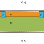
An ideal power device can control power flow without power dissipation. Here are the key characteristics:
- Zero Power Dissipation: An ideal power switch can operate without any power loss.
- Types of Loads:
- Inductive Loads: Motors and solenoids
- Resistive Loads: Heaters and lamp filaments
- Capacitive Loads: Transducers and LCD displays
- Pulsed Control: Power is often delivered through periodic turning on and off of the device.
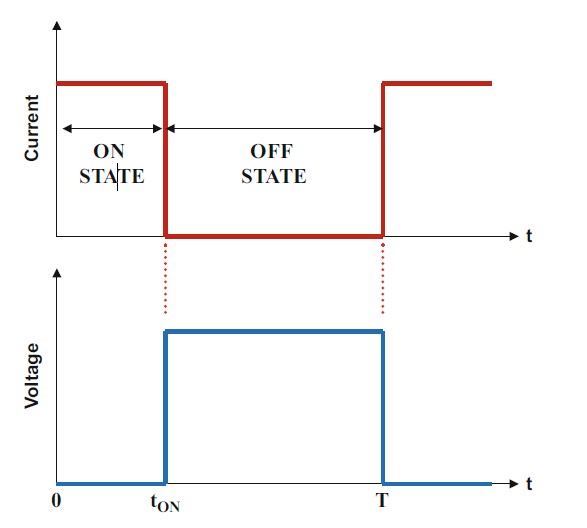
Characteristics of Ideal Waveforms
- The switch remains on for a time interval of tON and off for the remainder of the cycle, denoted as T.
- On-State Voltage Drop: For an ideal switch, the voltage drop during the on-state is zero, resulting in no power dissipation.
- Off-State Leakage Current: During the off-state, the leakage current is also zero, leading to no power loss.
- Instantaneous Transitions: Transitions between the on-state and off-state occur instantaneously, causing no power loss.
Typical Power Switching Waveforms
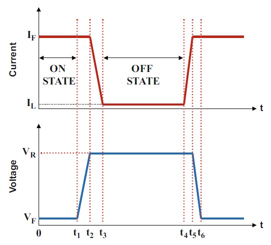
Typical power switches differ from ideal devices and exhibit power dissipation during various states of operation.
Power Dissipation in the On-State
- Voltage Drop ((V_F)): A typical switch has a non-zero voltage drop during the on-state.
- Power Dissipation Formula:
$$
P_L(on) = \delta \cdot I_F \cdot V_F
$$- Where:
- (I_F) = On-state current
- (\delta) = Duty cycle, calculated as:
$$
\delta = \frac{t_1}{T}
$$- (T) = Time period (the reciprocal of operating frequency)
- Where:
Power Dissipation in the Off-State
- Leakage Current ((I_L)): In the off-state, a leakage current exists which contributes to power dissipation.
- Power Dissipation Formula:
$$
P_L(off) = (1 – \delta) \cdot I_L \cdot V_R
$$- Where:
- (V_R) = Reverse bias voltage
- Where:
- Alternative Formula for Long Switching Times:
$$
P_L(off) = \frac{(t_4 – t_3) \cdot I_L \cdot V_R}{T}
$$
Considerations
- Negligible Off-State Losses: Typically, power dissipation in the off-state is small compared to other losses and can often be neglected.
- Impact of Temperature: At elevated temperatures or with Schottky contacts, off-state losses may become significant.
Power Dissipation During Switching
Power dissipation must be analyzed separately for turn-off and turn-on transients.
Turn-Off Transient
For inductive loads, the voltage across the switch rapidly increases to the DC supply voltage while the current decreases.
- Power Loss Formula:
$$
P_L(turn_off) = 0.5 \cdot (t_3 – t_1) \cdot I_F \cdot V_R \cdot f
$$- Where:
- (f) = Operating frequency
- Where:
Turn-On Transient
The power loss during the turn-on transition is analyzed similarly.
- Power Loss Formula:
$$
P_L(turn_on) = 0.5 \cdot (t_6 – t_4) \cdot I_F \cdot V_R \cdot f
$$
Total Power Dissipation
The total power dissipation in the switch combines all components:
$$
P_L(total) = P_L(on) + P_L(off) + P_L(turn_off) + P_L(turn_on)
$$
Frequency Considerations
- Low Operating Frequencies: At low frequencies, the on-state power loss is usually dominant, emphasizing the need for switches with low on-state voltage drops.
- High Operating Frequencies: At high frequencies, switching losses become more significant, leading to a demand for fast-switching devices with minimal transition times.
Conclusion
As power switch technology evolves, the overall power loss in optimized designs continues to decrease. This progress enhances the efficiency of power systems.