• Home
  • Courses
  • Machines
    • Transformer
    • AC Motors
      • Induction Motor
      • Synchronous Motor
    • DC Motor
    • DC Generator
  • Power System
    • Circuit Breaker
    • Switchgear
    • Substation
    • Control System
    • Measurement
  • Electronics
  • Blog
  • Contact
    • Contact Us
    • Privacy Policy
Have any question?
[email protected]
RegisterLogin
StudyElectrical.Com
  • Home
  • Courses
  • Machines
    • Transformer
    • AC Motors
      • Induction Motor
      • Synchronous Motor
    • DC Motor
    • DC Generator
  • Power System
    • Circuit Breaker
    • Switchgear
    • Substation
    • Control System
    • Measurement
  • Electronics
  • Blog
  • Contact
    • Contact Us
    • Privacy Policy

Basic Electrical

Understanding Power Factor Using a Horse and a Railcar

  • Categories Basic Electrical
Understand power factor using horse cart
A simple analogy is the best way to understand power factor. Please read what is power factor before reading this article. Beer mug analogy is already explained here.

In the figure, a horse is pulling a railroad car down a railroad track. The railroad tire are uneven, so the horse must pull the car from the side of the track. The horse is pulling the railroad car at an angle to the direction of the car’s travel.


IMG 20160724 224403
  • The power required to move the car down the track is the working Of real power (kW). The effort of the horse is the total or apparent power (kVA).


  • Due to the angle of the horse’s pull, not all of its effort is used to move the car down the track.The car will not move sideways, therefore, the sideways pull of the horse is wasted effort — the nonworking or reactive power (kVAr).


  • The angle of the horse’s pull is related to power factor, which is defined as the ratio of real power to apparent (total) power.
 
If the horse is led closer to the center of the track, the angle of side pull decreases and the real power approaches the value of the apparent power. Therefore, the ratio of real power to apparent power (the power factor) approaches one. As the power factor approaches one, the reactive (nonworking) power approaches zero.
 
In the ideal horse pulling the railcar analogy, if the reactive power (kVAr) is near zero, then real power (kW) and apparent power (kVA) would almost be equal, which means the horse would not waste as much energy pulling the car. The angle formed between real and apparent power would approach zero. The cosine of the angle would then approach one, resulting in a power factor that approaches one.
 
The closer a system’s power factor is to one, the more efficient the system is.

The Power Triangle

Reactive Power Triangle
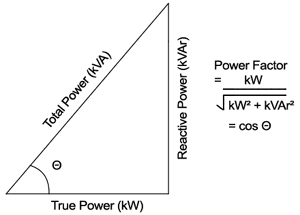
One way to illustrate the relationship between real power, apparent power, reactive power, and power factor is with a power triangle. As seen, only 70% of the current provided by electric utilities is being used to produce work.
 
For example. using the power triangle illustrated. if Real power = 100 kW and Apparent power = 142 kVA 


then Power Factor = 100/142 = 0.70 or 70%.


This indicates that only 70% of the current provided by the electrical utility is being used to produce useful work.

Related Articles

  • What is power factor
    What is Power Factor, Its Causes and How to Improve it?

    Simply stated, the Power Factor is the percentage of Apparent Power that does real work.…

  • protective zones in power system
    Protective Zones in Power Systems

    In this post, we will look into protective zones in the power system and why…

  • Types of Power plants
    Types of Power Plants

    What is the Power Plant? A power plant is an assembly of systems or subsystems…

  • Substation Relay
    Basics of Protective Relaying in Power System

    Protective relaying is necessary with almost every electrical plant, and no part of the power…

  • 4 2Bmajor 2Btypes 2Bof 2Bsubstations
    4 Major Types of Electrical Substations

      The assembly of the apparatus used to change some characteristic (e.g. voltage, a.c. to…

  • surge
    Voltage Surge in Power System

    What is Voltage Surge or Transient Voltage? The sudden rise in voltage for a very…

  • Share:
author avatar

Previous post

Primary and Back-up Protection in Power System

Next post

Oil Circuit Breakers - Types, Working and Construction

You may also like

Si units types advantages and disadvantages (1)
SI Units (International System of Units): Types, Advantages and Disadvantages
Electric current concept
Concept of Electric Charge and Current
dc voltage source
What is a Voltage Source? | DC and AC Voltage Sources Explained

Leave A Reply Cancel reply

Your email address will not be published. Required fields are marked *

Search Here

PCBWay

From Blog

universal motor construction
Construction of Universal Motors
Metal Clad Switchgear
Low Voltage Circuit Breakers – Design and Construction Basics
Arduino Digital Voltmeter
Arduino DC Digital Voltmeter
capacitive proximity sensor
5 Important Questions to Ask a Proximity Sensor Manufacturer

Categories

  • Alternator
  • Arduino
  • Basic Electrical
  • Battery
  • Books
  • Cables
  • Capacitor
  • Career
  • Circuit Breaker
  • Control System
  • DC Generator
  • DC Motor
  • Electric Vehicles
  • Electrical Circuits
  • Electrical Machines
  • Electrical Relays
  • Electrical Safety
  • Electronics
  • Embedded System
  • Exams
  • Generation
  • Guest Post
  • HVDC
  • Instrumentation
  • Interview Questions
  • Locomotives
  • Measurement
  • Microcontroller
  • Objective Questions
  • PCB
  • PLC
  • Power System
  • Projects
  • Signals and Systems
  • Single Phase Motors
  • Substation
  • Switchgear
  • Synchronous Motor
  • Three Phase Induction Motor
  • Transformer
  • Transmission Line
  • Uncategorized

Copyright © 2021 Study Electrical, Inc.

© StudyElectrical.Com 2021

Login with your site account

Lost your password?

Not a member yet? Register now

Register a new account

Are you a member? Login now