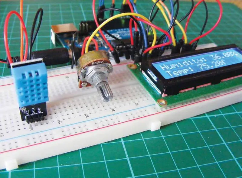
Weather stations are facilities on land or at sea that measure atmospheric conditions to provide weather forecasts and to study the weather. In this project the Arduino Weather Station measures temperature and humidity using DHT11 sensor and displays these values on an LCD display.
How Arduino Weather Station Works
| Parts Required | Libraries Required |
| Arduino board Breadboard Jumper wires 50k-ohm potentiometer 16×2 LCD screen (Hitachi HD44780 compatible) DHT11 humidity sensor | LiquidCrystal DHT |
DHT 11 Sensor
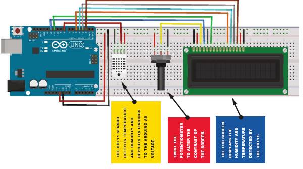
This project uses a relatively cheap DHT11 humidity sensor that measures both humidity and temperature. The sensor takes measurements from its environment using a capacitive humidity sensor and a resistive type temperature sensor. This reading is sent to the Arduino as voltage, and the Arduino converts it into readable values to display on the screen.
In order to get the best results, we recommend mounting your sensor on a wall that has a decent amount of open space on the outside of it. It’s best to mount your LCD screen indoors or to seal it in a clear, waterproof bag or case to keep it protected.
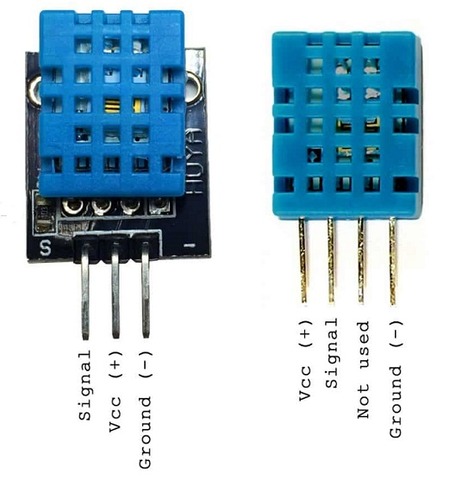
The DHT11 sensor comes with either four pins or three pins. In this project, you will not be using pin 3 of the sensor shown in figure, so either version will work.
Liquid Crystal Display
LCD (liquid crystal display) screens are composed of two sheets of polarizing material with liquid crystal solution encased between them. The current passing through the solution creates the image or, in this case, the characters.
For this project, you’ll need an LCD screen compatible with the Hitachi HD44780 driver. You can identify these screens by their 16-pin interface since there are many out there. In order to send characters to the LCD, we will use the LiquidCrystal library. The LiquidCrystal library maps the characters and uses the print.lcd command to display the message. The LCD screen needs to be prepared before you begin.
Building Arduino Weather Station
Step 1: Prepare the LCD screen
The LCD screen will probably require a bit of assembly. The screen should come with 16 holes and a separate strip of header pins. Break off a row of 16 pins from the strip of pins. Pins should be inserted into LCD holes with their shorter sides facing up. In order to attach them, you’ll need to solder them. To hold the strip in place, solder the far-right and far-left pins first and wait for them to set. After that, solder each pin one at a time, holding the soldering iron and solder to the pins as you go. It is only necessary to solder the pins for a few seconds; if you hold the iron for too long, they will be damaged.
Step 2: Connecting DHT11 Sensor
Start by preparing the LCD screen as directed above. Place the DHT11 sensor on your breadboard. As you look at the front of the DHT11, the pins are numbered 1 to 4 (or 3) from the left. Connect pin 1 directly to the +5V rail, pin 2 directly to Arduino pin 8, and pin 4 directly to GND.
| DHT11 | Arduino |
|---|---|
| Pin 1 | +5V |
| Pin 2 | Pin 8 |
| Pin 3 | Not used |
| Pin 4 | GND |
Step 3:
The LCD screen must be inserted into the breadboard and connected to the Arduino via the pins shown in table and Figure. Multiple connections will be made to the GND and +5V rails.
| LCD Screen | Arduino |
|---|---|
| 1 VSS | GND |
| 2 VDD | +5V |
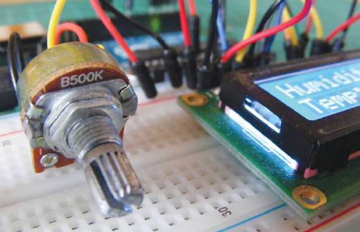
| 3 VO contrast | Potentiometer center pin |
| 4 RS | Pin 12 |
| 5 R/W | GND |
| 6 Enable | Pin 11 |
| 7 D0 | Not used |
| 8 D1 | Not used |
| 9 D2 | Not used |
| 10 D3 | Not used |
| 11 D4 | Pin 5 |
| 12 D5 | Pin 4 |
| 13 D6 | Pin 3 |
| 14 D7 | Pin 2 |
| 15 A BcL + | +5V |
| 16 K BcL – | GND |
Step 4:
Insert a potentiometer into the breadboard as shown in Figure 13-3 and connect the center pin to LCD pin 3. Connect one outer pin to the +5V rail and the other to the GND rail.
Step 5:
Remember to connect the power rails of the breadboard to Arduino GND and +5V. Confirm that your setup matches the circuit diagram, and upload the code below.
Arduino Sketch
In this sketch, the LiquidCrystal library is used, which is included with the Arduino IDE, and the DHT library must be downloaded and installed separately. The LCD library displays the readings on the screen, while the DHT library controls the sensor’s function.
/* Example testing sketch for various DHT humidity/temperature
sensors. Written by ladyada, public domain. */
#include <LiquidCrystal.h>
#include "DHT.h" // Call the DHT library
#define DHTPIN 8 // Pin connected to DHT
LiquidCrystal lcd(12, 11, 5, 4, 3, 2);
#define DHTTYPE DHT11 // Define the type of DHT module
DHT dht(DHTPIN, DHTTYPE); // Command to the DHT.h library
void setup() {
dht.begin(); // Start the sensor
lcd.begin(16, 2); // LCD screen is 16 characters by 2 lines
}
void loop() {
float h = dht.readHumidity(); // Value for humidity
float t = dht.readTemperature(); // Value for temperature
t = t * 9 / 5 + 32; // Change reading from Celsius to Fahrenheit
if (isnan(t) || isnan(h)) { // Check that DHT sensor is working
lcd.setCursor(0, 0);
lcd.print("Failed to read from DHT"); // If DHT is not working,
// display this
} else { // Otherwise show the readings on the screen
lcd.clear();
lcd.setCursor(0, 0);
lcd.print("Humidity: ");
lcd.print(h);
lcd.print("%");
lcd.setCursor(0, 1);
lcd.print("Temp: ");
lcd.print(t);
lcd.print("f");
}
}