A digital multimeter is an electronic instrument which can measure very precisely the dc and ac voltage, current (dc and ac), and resistance. All quantities other than dc voltage is first converted into an equivalent dc voltage by some device and then measured with the help of digital voltmeter.
The block diagram of a digital multimeter is shown below. The procedures of measurement of different quantities are described below.
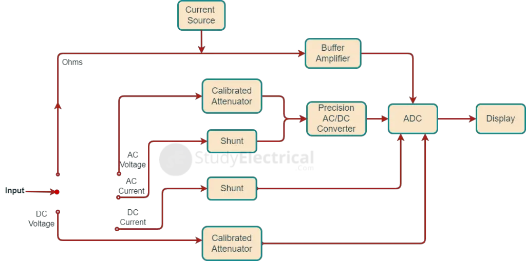
Voltage Measurement
For measurement of ac voltage, the input voltage, is fed through a calibrated, compensated attenuator, to a precision full-wave rectifier circuit followed by a ripple reduction filter. The resulting dc is fed to an Analog Digital Converter (ADC) and the subsequent display system. Many manufacturers provide the same attenuator for both ac and dc measurements.
Current Measurement
For current measurement, the drop across an internal calibrated shunt is measured directly by the ADC in the ‘dc current mode’, and after ac to dc conversion in the ‘ac current mode’. This drop is often in the range of 200 mV (corresponding to full scale).
Due to the lack of precision in the ac–dc conversions, the accuracy in the ac range is generally of the order of 0.2 to 0.5%. In addition, the measurement range is often limited to about 50 Hz at the lower frequency end due to the ripple in the rectified signal becoming a non-negligible percentage of the display and hence results in fluctuation of the displayed number. At the higher frequency end, deterioration of the performance of the ADC converter limits the accuracy.
In ac measurement the reading is often average or rms values of the unknown current. Sometimes for measurement of current, a current to voltage converter may also be used.
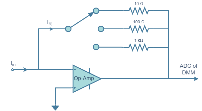
The current under measurement is applied to the summing junction at the input of the op-amp. The current in the feedback resistor IR is equal to the input current Iin because of very high input impedance of the op-amp. The current IR causes a voltage drop across one of the resistors, which is proportional to the input current Iin. Different resistors are employed for different ranges.
Resistance Measurement
For resistance measurement the digital multimeter operates by measuring the voltage across the externally connected resistance, resulting from a current forced through it from a calibrated internal current source.
The accuracy of the resistance measurement is of the order of 0.1 to 0.5% depending on the accuracy and stability of the internal current sources. The accuracy may be proper in the highest range which is often about 10 to 20 MΩ. In the lowest range, the full scale may be nearly equal to>200 Ω with a resolution of about 0.01 Ω for a 4½ digit digital multimeter. In this range of resistance measurement, the effect of the load resistance will have to be carefully considered.
How to Measure Voltage Using Digital Multimeter?
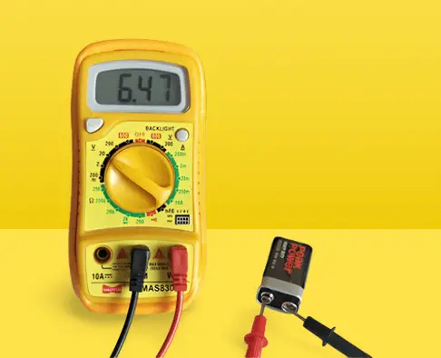
DC Voltage Measurements
To measure DC voltage, we place the Red lead into the V Ω COM port. Turn the dial or switch to VDC or V. If it is a manual ranging meter set it for the proper range.
As in the example below, we want to measure a 9V battery so the best range would be the 20 V range. If you have an auto-ranging meter you only need to set the function on the dial to VDC or V.
AC Voltage Measurement
To measure AC voltage, we place the Red lead into the V Ω port and black lead into the COM port. Turn the dial or switch to VAC or V. If it is a manual ranging meter set it for the proper range.
As an example the meter would be set to the 200 V range to measure a 120V outlet. If you have an auto-ranging meter you only need to set function to VAC or V .
Remember that it is always a good practice to connect the black lead first then the red.